
So, what is electromagnetic induction? Electromagnetic induction is the creation of an electromotive force—usually described as an induced voltage—when the magnetic flux through a conductor or circuit changes.

It is one of the most important principles in electrical engineering. Generators, transformers, induction cookers, wireless chargers, guitar pickups, metal detectors and many high-voltage power supplies all depend on it.
Electromagnetic induction is also essential inside the High Frequency Plasma Generator. Rapidly changing current in the primary winding around the flyback core creates changing magnetic flux, which induces a much higher voltage in the secondary winding.
📚 High Frequency Plasma Learning Centre
📘 Lesson 16 of 24 — What Is Electromagnetic Induction?
Previous lesson: Lesson 15 — What Is a Magnetic Field?
Next lesson: Lesson 17 — What Is Voltage? (Coming Soon)
Estimated reading time: 18–22 minutes
Difficulty: 🟢 Beginner to Intermediate
What You’ll Learn
By the end of this lesson, you will understand:
- What electromagnetic induction is. ✔
- What Michael Faraday discovered. ✔
- What magnetic flux means. ✔
- Why changing flux—not simply the presence of a magnet—creates an induced voltage. ✔
- The four main ways magnetic flux can change. ✔
- What Faraday’s law tells us. ✔
- Why the minus sign in Faraday’s law represents Lenz’s law. ✔
- The difference between induced voltage and induced current. ✔
- What self-inductance and mutual inductance mean. ✔
- How generators and transformers use induction. ✔
- Why a transformer needs changing current. ✔
- How the ZVS driver and flyback stage use induction. ✔
- Why induction is different from capacitive coupling. ✔
- How induced signals can be measured safely. ✔
The Short Answer: What Is Electromagnetic Induction?
Electromagnetic induction occurs when a changing magnetic flux produces an electric field and an electromotive force, or emf.
The magnetic field itself does not merely have to exist. Something about the magnetic flux through the circuit must change.
For example, an induced voltage can be produced by:
- Moving a magnet toward or away from a coil.
- Moving a coil through a magnetic field.
- Changing the strength of the field.
- Rotating the coil relative to the field.
- Changing the area of the loop exposed to the field.
- Changing the current in a nearby coil.
If the conductor forms a closed circuit, the induced emf may drive a current. If the circuit is open, an induced voltage can still be present even though no continuous current flows.
The key idea is:
A changing magnetic flux induces an emf.
Michael Faraday’s Discovery
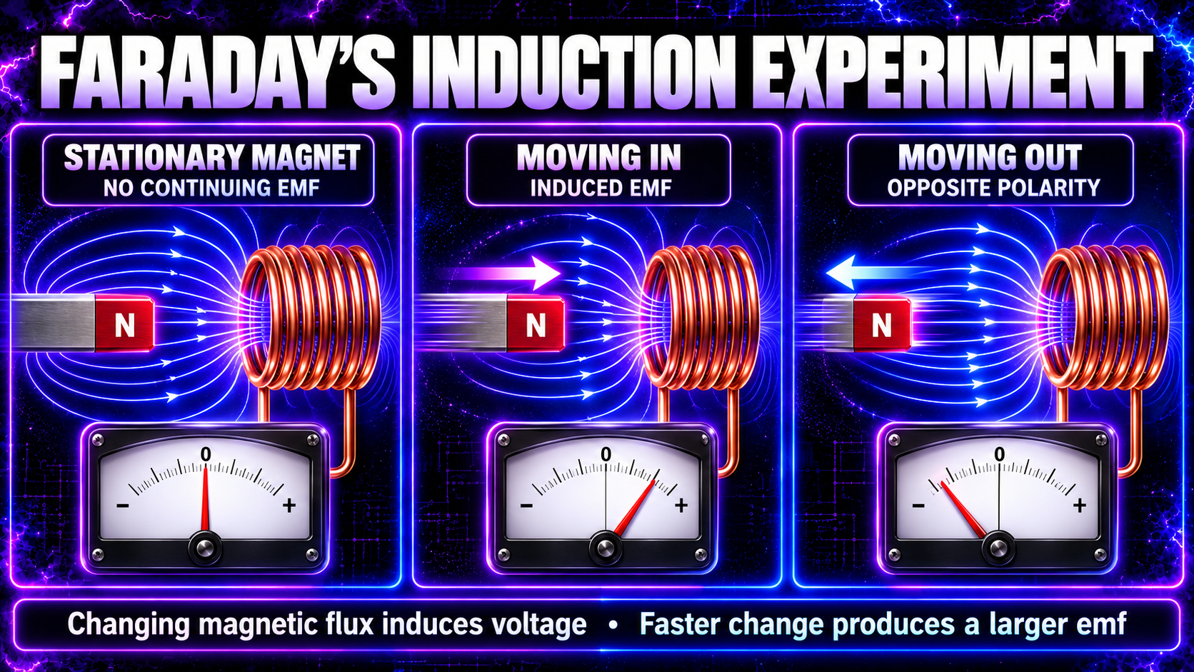
In 1831, Michael Faraday performed experiments that revealed the connection between changing magnetic fields and electricity.
He found that moving a magnet into a coil caused a meter connected to the coil to deflect. Pulling the magnet out caused a deflection in the opposite direction. Holding the magnet still produced no continuing deflection.
Faraday also used two nearby coils. When he switched current on or off in the first coil, a brief current appeared in the second. Once the current in the first coil became steady, the effect in the second disappeared.
These observations established several essential points:
- Relative motion between a magnet and coil can induce voltage.
- Reversing the motion reverses the induced polarity.
- Faster change produces a larger induced emf.
- A steady magnetic situation produces no continuing induced emf.
- A changing current in one circuit can induce voltage in another circuit.
Faraday described these results using the idea of magnetic lines of force. Modern physics expresses the same principle using magnetic flux and Faraday’s law.
What Is Magnetic Flux?
Magnetic flux describes how much magnetic field passes through a surface.
It is represented by the Greek letter:
Φ — phi
For a uniform magnetic field passing through a flat loop:
Φ = BA cos θ
Where:
- Φ is magnetic flux, measured in webers (Wb).
- B is magnetic flux density, measured in tesla (T).
- A is the area of the loop in square metres.
- θ is the angle between the magnetic field and a line perpendicular to the loop.
The angle is important. Flux is greatest when the field passes straight through the face of the loop. It becomes zero in the ideal model when the field runs parallel to the plane of the loop.
Magnetic flux is not a physical substance flowing through the wire. It is a mathematical way of describing the magnetic field passing through an area.
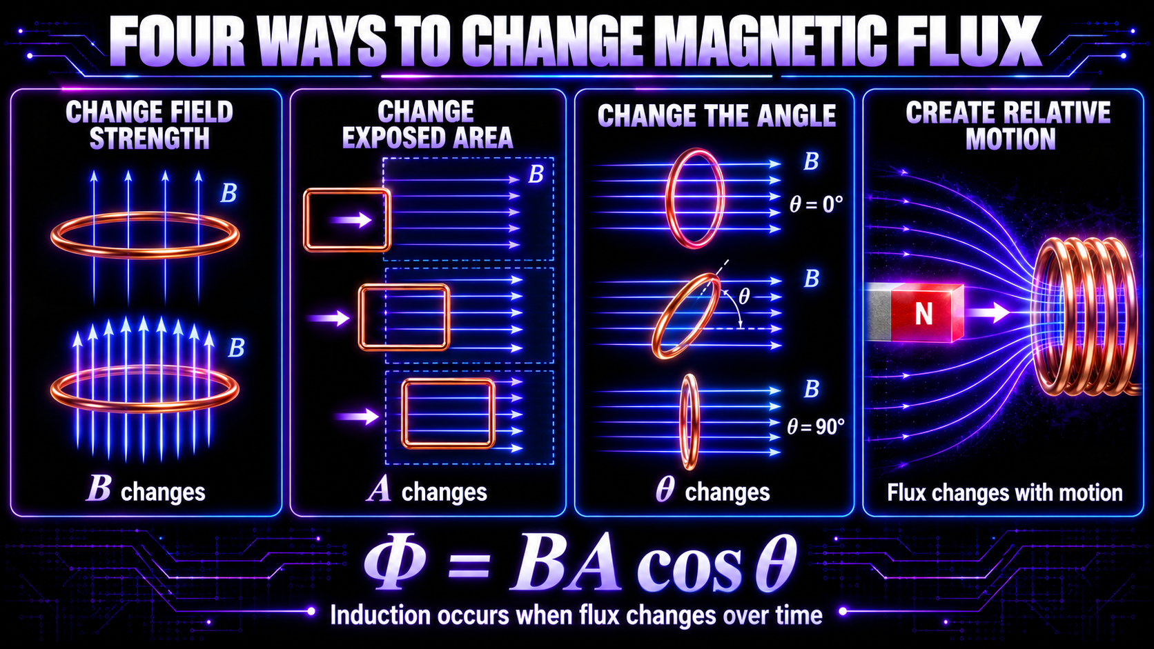
Four Main Ways to Change Magnetic Flux
Because flux depends on field strength, area and angle, it can be changed in several ways.
1. Change the magnetic field strength
Increasing or decreasing the field passing through a stationary loop changes the flux. A nearby electromagnet driven with changing current is one way to do this.
2. Change the exposed area
Moving a loop into or out of a region containing a magnetic field changes the amount of its area threaded by the field.
3. Change the angle
Rotating a loop changes the angle between the field and the loop’s area. This is the basic principle used in many electric generators.
4. Create relative motion
Moving a magnet relative to a coil changes the field through the coil. Moving the coil relative to the magnet can produce the same result.
All four methods have something in common: the flux changes over time.
What Is Faraday’s Law?
Faraday’s law gives the magnitude and polarity of the induced emf:
ε = −N dΦ/dt
Where:
- ε is the induced emf in volts.
- N is the number of turns in the coil.
- dΦ/dt is the rate at which magnetic flux changes.
- The minus sign represents Lenz’s law.
In plain English:
- More turns can produce a larger induced voltage.
- A faster change of flux produces a larger induced voltage.
- A stronger magnetic-field change can produce a larger induced voltage.
- A larger effective coil area can intercept more flux.
Faraday’s law does not say that a strong static field must produce a large voltage. A strong field that does not change can produce zero continuing induced emf in a stationary loop.
Likewise, even a modest field can produce a noticeable induced emf if its flux changes rapidly enough and the coil has many turns.
Why Is EMF Measured in Volts?
The term electromotive force is historical. Despite the word force, emf is not measured in newtons. It is measured in volts.
EMF describes the energy supplied per unit charge around a circuit. It behaves like a source voltage, although the physical origin may be different from the chemical action inside a battery.
An important distinction is:
- Induced emf or voltage may exist across an open coil.
- Induced current requires a closed conducting path.
The size of the current then depends on the induced voltage and the impedance of the circuit.
A sensitive voltmeter can therefore detect an induced voltage even when very little current is flowing.
What Is Lenz’s Law?
Lenz’s law determines the direction of an induced emf and current:
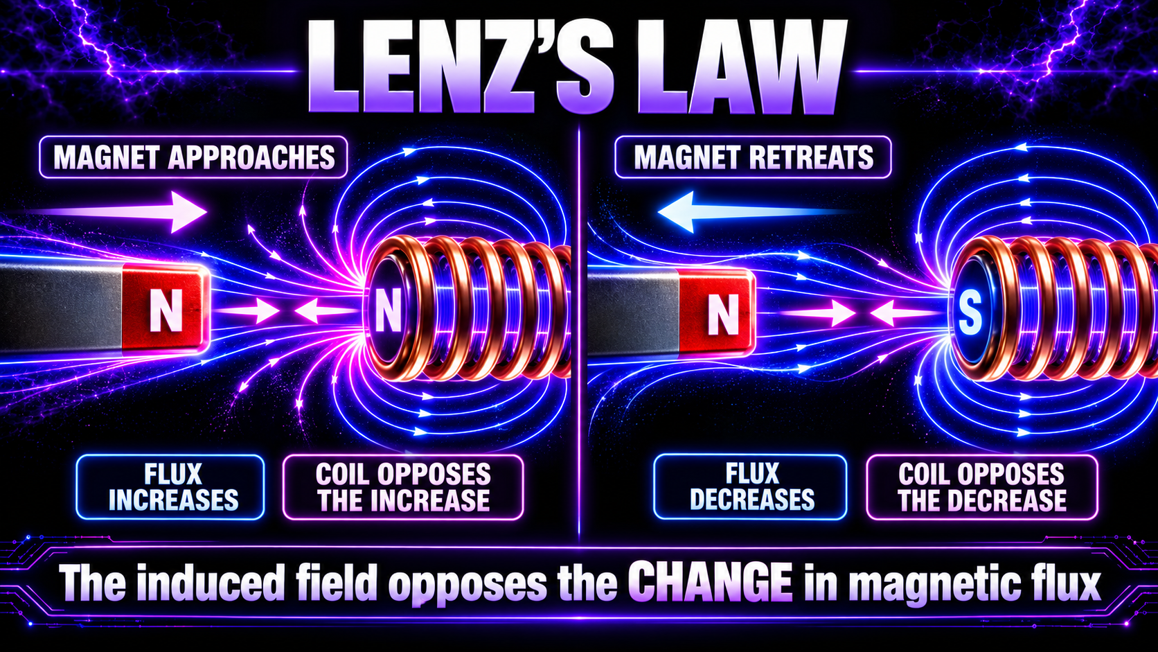
The induced effect acts in a direction that opposes the change in magnetic flux that produced it.
The word change matters. The induced field does not always oppose the original magnetic field. It opposes the increase or decrease in flux.
When a north pole approaches a coil
The magnetic flux through the coil increases. The induced current creates a magnetic field that resists that increase. The near face of the coil behaves like a north pole, opposing the approaching north pole.
When the north pole moves away
The flux through the coil decreases. The induced current reverses so that its field tries to maintain the original flux. The near face behaves like a south pole, attracting the retreating north pole.
Lenz’s law is a consequence of conservation of energy. If the induced field assisted the change rather than opposed it, a magnet could accelerate into a coil while producing electrical energy without an energy input.
Magnet and Coil: What Happens in Each Situation?
| Situation | Magnetic flux through coil | Induced emf |
|---|---|---|
| Magnet stationary relative to coil | Constant | Zero after any transient |
| Magnet moving toward coil | Changing | Present |
| Magnet moving away from coil | Changing in opposite sense | Present with opposite polarity |
| Magnet moving faster | Changes faster | Larger magnitude |
| Magnet pole reversed | Field direction reversed | Polarity reversed |
| Coil moved instead of magnet | Changing through relative motion | Present |
The same principle applies whether the magnet or the coil moves. What matters is the changing relationship between the magnetic field and the conducting loop.
What Is Motional EMF?
When a conductor moves through a magnetic field, charges inside it experience magnetic force. Positive and negative charges can be pushed toward opposite ends, creating a potential difference.
For a straight conductor of length ℓ moving perpendicular to a uniform field:
ε = Bℓv
Where:
- B is magnetic flux density.
- ℓ is the active conductor length.
- v is its speed through the field.
This is called motional emf.
It is closely related to Faraday’s law. As the conductor moves, the area of the circuit exposed to the magnetic field changes, so the magnetic flux changes.
Motional emf is central to rotating generators, moving-coil sensors and many laboratory demonstrations.
How Does an Electric Generator Use Induction?
An electric generator converts mechanical energy into electrical energy.
In a simple model:
- A coil rotates in a magnetic field.
- The angle between the coil and field changes continuously.
- The magnetic flux through the coil rises, falls and reverses.
- An alternating emf is induced.
Rotating the coil faster increases the rate of flux change and therefore increases the induced emf, assuming other conditions stay the same.
The energy does not appear from nowhere. Mechanical work must be supplied to turn the generator against the opposing electromagnetic effects described by Lenz’s law.
Power-station generators, wind turbines, hydroelectric generators and small bicycle dynamos use more sophisticated versions of this same principle.
What Is Mutual Inductance?
Mutual inductance occurs when changing current in one circuit induces an emf in another circuit.
Imagine two coils placed close together:
- Current in coil 1 changes.
- Its magnetic field changes.
- The magnetic flux through coil 2 changes.
- An emf is induced in coil 2.
The relationship can be written:
ε₂ = −M dI₁/dt
Where M is the mutual inductance between the circuits.
Mutual inductance depends on:
- The number of turns in each coil.
- Their separation.
- Their orientation.
- The amount of shared magnetic flux.
- The core material and geometry.
Two coils wound around the same magnetic core can be coupled far more strongly than two widely separated air-core coils.
What Is Self-Inductance?
A changing current can also induce an emf in the same circuit that produced the changing magnetic field. This is self-inductance.
The induced emf is:
ε = −L dI/dt
Where L is inductance, measured in henries (H).
An inductor resists rapid changes in current. This does not mean it permanently blocks current. Instead, it produces a back emf while current is changing.
When current builds, energy is stored in the magnetic field. When current falls, the field collapses and that stored energy can be returned to the circuit.
The faster the current tries to change, the larger the induced back emf can become. This is why rapidly interrupting current through a coil can create a high-voltage transient.
How Does a Transformer Use Electromagnetic Induction?
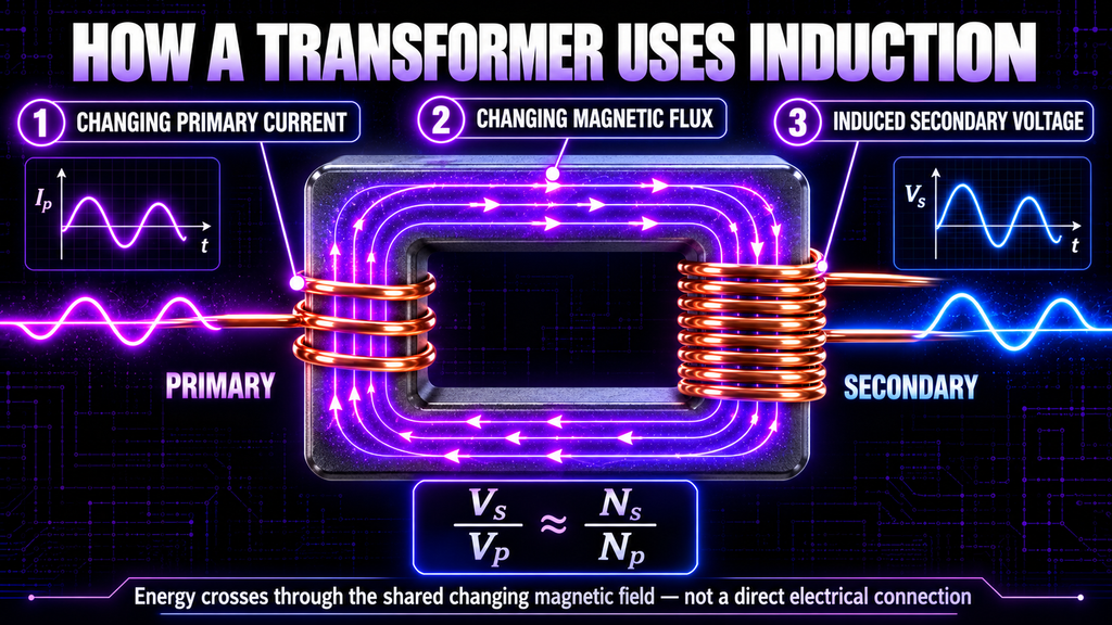
A transformer uses mutual induction to transfer energy between windings without a direct conductive connection between them.
The basic sequence is:
- Alternating or switched current flows in the primary winding.
- The primary creates changing magnetic flux in the core.
- The core guides much of that changing flux through the secondary winding.
- The changing flux induces voltage in the secondary.
For an ideal conventional transformer:
Vₛ / Vₚ = Nₛ / Nₚ
Where:
- Vₛ is secondary voltage.
- Vₚ is primary voltage.
- Nₛ is secondary turns.
- Nₚ is primary turns.
More secondary turns than primary turns gives a step-up transformer. Fewer secondary turns gives a step-down transformer.
Real transformers have winding resistance, leakage flux, core losses, parasitic capacitance and limits set by frequency, waveform and core material. The ideal turns-ratio equation is therefore a starting point, not a complete description of every pulsed transformer.
Why Does a Transformer Need Changing Current?
A constant direct current produces a steady magnetic field after its initial rise. Once the flux becomes constant, dΦ/dt becomes zero and no continuing secondary emf is induced.
There may be a brief induced pulse when DC is first connected and another of opposite polarity when it is disconnected, because the current and flux change during those moments.
To operate continuously from a DC supply, an electronic circuit must switch, chop or alternate the current through the primary. That is one of the jobs performed by the ZVS driver in the High Frequency Plasma Generator.
The important chain is:
DC input → electronic switching → changing primary current → changing core flux → induced secondary voltage
What Does ZVS Mean?
ZVS commonly means zero-voltage switching.
It describes a switching approach designed so that power transistors change state when the voltage across them is near zero. Under suitable conditions, this can reduce switching loss and stress compared with hard switching.
In a resonant ZVS driver used with a flyback transformer:
- The DC supply powers the switching circuit.
- The switches alternately drive current through the external primary winding.
- The primary current and magnetic field change rapidly.
- Changing flux in the flyback core induces voltage in the secondary.
The actual waveform is not necessarily a perfect sine wave. It depends on the circuit, transformer, supply, load, component tolerances and operating conditions.
How Does the Flyback Transformer Produce High Voltage?
A flyback transformer contains a primary side with relatively few turns and a secondary with many fine-wire turns. It normally uses a ferrite core suited to high-frequency operation.
In the plasma generator’s configuration, external primary windings driven by the ZVS circuit create changing flux in the flyback core. That changing flux links the internal secondary winding and induces a high voltage.
The high secondary turns count contributes to the voltage increase, but a flyback stage is not always described completely by the simple mains-transformer turns ratio. Resonance, switching waveform, core properties, coupling, leakage inductance, parasitic capacitance, load and any internal rectifier or winding arrangement can affect the output.
The essential principle remains Faraday’s law:
Rapidly changing magnetic flux through many secondary turns produces a large induced emf.
Electromagnetic Induction in the High Frequency Plasma Generator
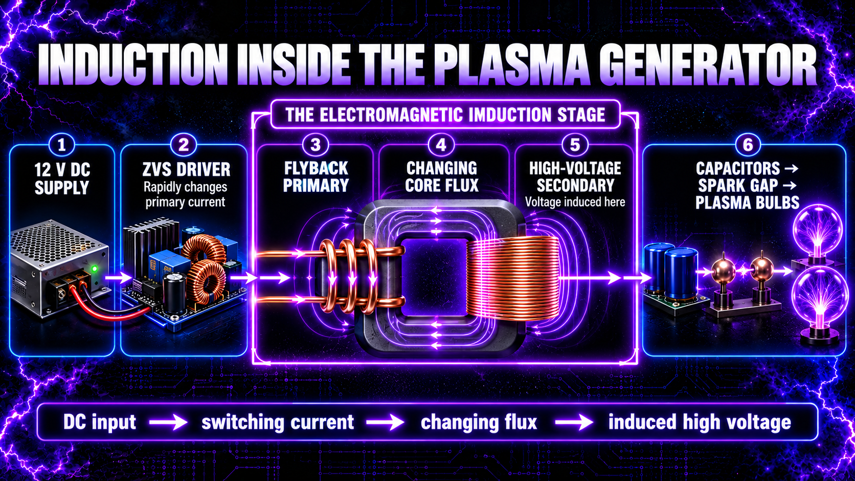
The power chain can be understood as a series of different energy-storage and switching stages.
Stage 1: 12-volt DC supply
The supply provides electrical energy to the driver. Steady DC alone would not create a continuous transformer output.
Stage 2: ZVS driver
The driver switches the DC into rapidly changing current through the flyback primary windings.
Stage 3: Flyback transformer
Changing primary current creates changing magnetic flux in the ferrite core. Mutual induction produces a much higher voltage in the secondary winding.
Stage 4: Capacitor banks
The high-voltage output charges the capacitor network. Capacitors store energy mainly in an electric field rather than a magnetic field.
Stage 5: Spark gap
When the voltage across the gap becomes sufficient for breakdown, the gas becomes ionised and the capacitors can discharge through a short, intense pulse.
Stage 6: Output circuit and plasma bulbs
The pulsed, high-frequency electrical output produces changing electric fields and current paths. These fields help excite and ionise the gas inside the bulbs.
Induction is therefore fundamental to producing the flyback’s high voltage, but it is not the only process in the complete machine. Capacitive energy storage, spark-gap switching, resonance, electric-field coupling and gas ionisation also have distinct roles.
Does the Spark Gap Create Electromagnetic Induction?
The spark gap is primarily a fast electrical switch.
When it conducts, current can rise and fall extremely quickly. Those rapid current changes create rapidly changing magnetic fields around the discharge loop. Nearby conductors may therefore experience induced voltages.
This means induction can occur around the spark-gap circuit, but the spark itself is not a transformer. The spark forms because the electric field across the gap becomes strong enough to cause gas breakdown.
The rapid discharge can also excite oscillations in circuits containing capacitance and inductance. These oscillations may contain a broad range of frequency components, depending on circuit geometry and damping.
Inductive Coupling Versus Capacitive Coupling
These two mechanisms are often confused.
| Feature | Inductive coupling | Capacitive coupling |
|---|---|---|
| Main changing field | Magnetic field | Electric field |
| Typical structure | Two coils or current loops | Two conductive surfaces separated by an insulator |
| Key circuit property | Mutual inductance | Capacitance |
| Requires changing signal | Yes for continuous transfer | Yes for continuous AC coupling through an insulator |
| Common example | Transformer | Capacitive touch sensor |
Inside the flyback transformer, energy transfer from primary to secondary is predominantly inductive.
Across the glass wall of a plasma bulb, electric-field or capacitive coupling can be especially important. The glass is an insulator, yet a changing electric field can extend through it and influence charge inside the gas.
Calling both effects simply “frequency transfer” hides the different physics involved.
Does Higher Frequency Increase Induction?
Faraday’s law depends on the rate of change of flux. If the same flux swing occurs more rapidly, the induced emf can increase.
However, higher frequency does not automatically guarantee a larger useful output. Real circuits introduce additional effects:
- Core losses can rise.
- Skin effect increases conductor resistance.
- Parasitic capacitance becomes more important.
- Leakage inductance affects coupling.
- Switching losses and heating can increase.
- Resonance can amplify or reduce particular responses.
- The transformer core can approach saturation under unsuitable conditions.
Frequency must therefore be considered together with voltage, current, waveform, turns, core material, geometry, load and thermal limits.
What Are Eddy Currents?
Electromagnetic induction can create circulating currents inside a bulk conductor. These are called eddy currents.
Eddy currents produce their own magnetic fields and can cause:
- Heating.
- Magnetic drag or braking.
- Energy loss inside transformer cores.
- Detection signals in metal detectors.
They are useful in induction cookers, non-contact braking, material testing and some sensors. In transformers, unwanted eddy-current loss is reduced by using laminated metal cores or ferrite materials with high electrical resistance.
The core in a high-frequency flyback transformer is normally ferrite because its magnetic and electrical properties are suitable for operation well above mains frequency.
What Is Back EMF?
Back emf is an induced voltage that opposes the change that produced it.
In an inductor, rising current produces a back emf that resists the rise. When the current falls, the induced voltage reverses in an attempt to keep current flowing.
Back emf appears in motors as well. As a motor turns, its coils move through magnetic fields and generate an emf opposing the applied voltage.
The idea follows directly from Lenz’s law. It is also why switching inductive loads can create unexpectedly high voltage transients.
Protective components and suitable circuit design are therefore important when switching coils, relays, motors and transformers.
How Can Induction Be Demonstrated Safely?
A simple low-energy demonstration uses a small permanent magnet, a coil of insulated wire and a sensitive meter.
- Move the magnet toward the coil: the meter deflects.
- Stop the magnet: the reading returns toward zero.
- Pull the magnet away: the meter deflects in the opposite direction.
- Move it faster: the deflection becomes larger.
This demonstrates change, direction and rate without using a high-voltage supply.
Another safe classroom demonstration uses two low-voltage coils. Switching current in one coil creates a brief induced signal in the other.
Experiments involving mains electricity, flyback transformers, charged capacitors or spark gaps require appropriate professional competence, guarding, isolation, discharge procedures and test equipment.
How Can an Induced Signal Be Measured?
The right instrument depends on the expected voltage, frequency and source impedance.
Sensitive voltmeter
A digital or analogue meter can show low-frequency induction from a moving magnet and coil.
Oscilloscope
An oscilloscope can display induced waveforms and polarity, but its probe and grounding arrangement must be appropriate for the circuit. Connecting an earth-referenced scope incorrectly to a high-voltage or floating circuit can cause damage, shock or fire.
Search coil
A small pickup coil produces voltage in response to changing magnetic flux. It can help locate changing magnetic fields and compare relative signals.
Spectrum analyser
A suitable near-field loop can show frequency components, but the display is not automatically a calibrated measurement of magnetic flux density or induced voltage in the equipment being tested.
A TinySA can be useful for comparative spectrum observations when used with an appropriate pickup probe and safe separation. It must never be directly connected to an unknown high-voltage output.
Common Myths About Electromagnetic Induction
Myth 1: A magnet beside any wire continuously produces electricity
False. There must be a changing magnetic flux through the relevant circuit.
Myth 2: Only the magnet can move
False. Moving the coil, changing the field strength or rotating the loop can also change flux.
Myth 3: EMF is a mechanical force
False. Electromotive force is measured in volts, not newtons.
Myth 4: Induced voltage guarantees a large current
False. Current also depends on whether the circuit is closed and on its impedance.
Myth 5: A transformer works with steady DC
False. A transformer needs changing magnetic flux for continuous energy transfer. Electronic switching can convert DC into changing current.
Myth 6: Induction and resonance are the same thing
False. Induction is the creation of emf by changing flux. Resonance is the enhanced response of a system near one of its natural frequencies. They can occur together but remain distinct concepts.
Myth 7: Inductive and capacitive coupling are identical
False. Inductive coupling is primarily associated with changing magnetic flux; capacitive coupling is associated with changing electric fields between conductive regions.
Myth 8: The spark gap produces the flyback’s high voltage
False. The ZVS-driven flyback stage produces high voltage through induction. The spark gap switches stored electrical energy later in the chain.
Frequently Asked Questions
What is electromagnetic induction in simple words?
It is the production of voltage when the magnetic flux through a conductor or circuit changes.
Who discovered electromagnetic induction?
Michael Faraday demonstrated the principle experimentally in 1831. Joseph Henry independently made closely related discoveries during the same period.
Does a stationary magnet induce voltage in a stationary coil?
Not continuously. If the magnetic flux remains constant, Faraday’s law gives no continuing induced emf.
Why does moving the magnet faster increase the voltage?
Faster motion normally changes the flux more quickly, increasing dΦ/dt.
What does the minus sign in Faraday’s law mean?
It represents Lenz’s law: the induced effect opposes the change in flux that caused it.
Can voltage be induced without current?
Yes. An open coil can have induced voltage across its terminals. Continuous current requires a closed path.
Why do coils have many turns?
Each turn links magnetic flux. If the turns are connected in series with the same orientation, their induced emfs add.
Can DC power a transformer?
Steady DC cannot produce continuous transformer action. A switching circuit can convert DC into rapidly changing current that drives a transformer.
What is the difference between self-inductance and mutual inductance?
Self-inductance is induced emf in the same circuit whose current is changing. Mutual inductance is induced emf in a separate nearby circuit.
Is a flyback transformer the same as an ordinary mains transformer?
Both rely on electromagnetic induction, but flyback transformers are designed for high-frequency or pulsed operation and can have different winding, core, rectification and energy-transfer behaviour.
Where does induction happen in the High Frequency Plasma Generator?
Its clearest role is between the ZVS-driven primary winding and the high-voltage secondary of the flyback transformer. Rapid current changes elsewhere can also induce signals in nearby conductors.
Does the glass plasma bulb use induction?
Magnetic induction may be present around changing currents, but electric-field and capacitive coupling through the glass are especially important in this system. The mechanisms should not be treated as identical.
Can I connect a meter directly to the high-voltage output?
No ordinary meter, oscilloscope or spectrum analyser should be connected directly to an unknown high-voltage output. Use appropriately rated specialist equipment and competent high-voltage measurement practices.
What Have We Learned?
Electromagnetic induction is the production of an emf when magnetic flux changes.
Magnetic flux depends on magnetic field strength, area and orientation. Moving a magnet, moving a conductor, rotating a coil, changing the field strength or changing the exposed area can all produce induction.
Faraday’s law shows that induced emf depends on the rate of flux change and the number of coil turns. Lenz’s law determines polarity: the induced effect always opposes the change that caused it.
Generators use mechanical motion to change flux and create electrical output. Transformers use changing current in one winding to induce voltage in another. Self-inductance produces back emf in the same changing-current circuit.
In the High Frequency Plasma Generator, the ZVS driver changes current through the primary winding around the flyback core. The resulting changing magnetic flux induces high voltage in the secondary. The capacitor banks then store electrical energy, while the spark gap acts as a rapid switch and the output fields help excite plasma in the bulbs.
Understanding induction therefore connects the magnetic field from Lesson 15 to voltage, the subject of Lesson 17.
🧠 Key Takeaways
- Electromagnetic induction requires changing magnetic flux.
- A static magnetic situation produces no continuing induced emf.
- Magnetic flux depends on field strength, area and orientation.
- Faraday’s law is ε = −N dΦ/dt.
- More turns and faster flux change can increase induced voltage.
- Lenz’s law determines the direction of the induced effect.
- Induced voltage can exist without a closed-circuit current.
- Mutual inductance transfers energy between circuits through changing flux.
- Self-inductance creates back emf in the same circuit.
- Generators and transformers both rely on induction.
- Steady DC must be switched or alternated to drive a transformer continuously.
- The ZVS and flyback stage uses induction to produce high voltage.
- Capacitive coupling and inductive coupling are different mechanisms.
- High-voltage measurement requires specialised equipment and safe procedures.
🔬 Electromagnetic Induction Fact
Holding a strong magnet completely still inside a coil produces no continuing induced voltage. A weaker magnet moving rapidly can create a larger momentary voltage because the decisive factor is the rate of change of magnetic flux.
Continue Your Learning Journey
Previous: Lesson 15 — What Is a Magnetic Field?
Next: Lesson 17 — What Is Voltage? (Coming Soon)
In Lesson 17, we will explore what voltage actually measures, how potential difference moves charge and why high voltage does not automatically mean high current or high power.
Further Reading
- OpenStax: Faraday’s Law
- OpenStax: Lenz’s Law
- OpenStax: Motional EMF
- OpenStax: Mutual Inductance
- OpenStax: Motors, Generators and Transformers
- NASA: Electromagnetic Induction
Learn More About High-Frequency Plasma
Explore the High Frequency Plasma Learning Centre for beginner-friendly lessons about plasma, spark gaps, frequency, resonance, ionisation, electric fields, magnetic fields and high-voltage technology.
For product information, visit the High Frequency Plasma Generator website.
To ask questions and meet other people interested in plasma technology, join the free High Frequency Plasma Community Group on Telegram.
Disclaimer
The information in the High Frequency Plasma Learning Centre is provided for general educational purposes to explain the science, history and engineering of plasma and high-frequency electrical technology.
High-voltage and plasma equipment can cause serious electrical shock, burns, fire, electromagnetic interference and equipment damage. Capacitors may retain dangerous stored energy after power has been disconnected. Inductive circuits can also produce unexpectedly high voltage when current is interrupted. This lesson explains scientific principles; it is not a construction, modification, measurement or servicing guide.
Magnetic and electromagnetic fields can interfere with pacemakers, implanted electronic devices, magnetic storage media and sensitive equipment. People who are pregnant or who use a pacemaker or other implanted electronic device should not operate or remain close to this equipment. Follow the manufacturer’s safety instructions and obtain appropriate professional advice.
The High Frequency Plasma Generator is intended for educational, experimental, research, meditation, relaxation and general wellness purposes only. It is not a medical device and is not intended to diagnose, treat, cure, mitigate or prevent any disease or medical condition.
Always seek advice from a suitably qualified healthcare professional regarding medical concerns.
🎉 Lesson Complete
Congratulations!
You have now completed:
📘 Lesson 16 of 24
What Is Electromagnetic Induction? Faraday’s Law, Transformers and High Voltage Explained
You now understand how changing magnetic flux creates voltage and why this principle is essential to generators, transformers and the flyback stage inside a high-frequency plasma system.