
📘 Lesson 10 of 24 — What Are Electrical Oscillations?
Previous lesson: Lesson 9 — What Is Resonance?
Next lesson: Lesson 11
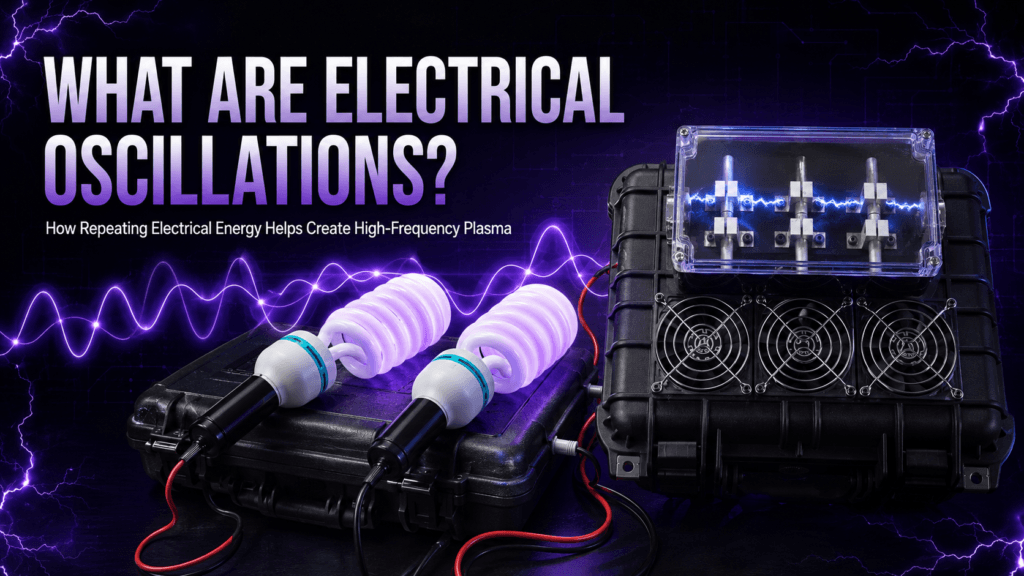
Electrical oscillations are one of the most important principles behind high-frequency electrical technology.
They occur inside radios, transmitters, electronic signal generators, resonant circuits and traditional spark-gap plasma systems. Although the term may sound technical, the basic idea is relatively simple.
An electrical oscillation is a repeated change in voltage, current or electric charge over time.
Instead of electricity travelling steadily in one direction, the electrical conditions within a circuit rise, fall and may repeatedly reverse direction. When this happens many times every second, the circuit is producing electrical oscillations.
In my High Frequency Plasma Generator, rapidly changing electrical energy is produced through the interaction of the high-frequency producer, capacitor network, circuit inductance and spark gap. These changes help energise the gas inside the two plasma bulbs.
This lesson explains what electrical oscillations are, how they begin and why they are so important in traditional spark-gap plasma technology.
What Does “Oscillation” Mean?
An oscillation is any movement or change that repeats around a central or resting point.
Familiar examples include:
- A pendulum swinging from side to side
- A guitar string vibrating after it is plucked
- A spring moving backwards and forwards
- Sound waves causing air pressure to rise and fall
- Water moving up and down in a wave
Electrical oscillations follow a similar principle, but instead of a physical object visibly moving, electrical quantities are changing.
These quantities can include:
- Voltage
- Current
- Electric charge
- Electric fields
- Magnetic fields
Because this activity can happen extremely quickly, we cannot usually see the individual electrical cycles directly. We may instead observe their effects through an oscilloscope, spectrum analyser, radio receiver, spark discharge or glowing plasma bulb.
A Simple Definition of Electrical Oscillations
Electrical oscillations are repeated variations in electrical voltage, current or charge within a circuit.
In a basic oscillating circuit, electrical energy can move between two forms:
- Energy stored in an electric field
- Energy stored in a magnetic field
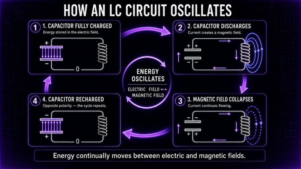
A capacitor stores energy in an electric field, while an inductor stores energy in a magnetic field. When capacitance and inductance interact, energy can move backwards and forwards between them.
This repeated exchange creates an electrical oscillation.
A useful comparison is a pendulum. At the highest point of its swing, a pendulum stores potential energy. As it falls, that energy becomes motion. It then rises on the opposite side, slows down and changes direction.
In an electrical circuit, the equivalent process occurs between the electric field of the capacitor and the magnetic field associated with current flowing through the circuit’s inductance.
Educational physics references describe an ideal LC circuit in exactly this way: energy repeatedly transfers between the capacitor’s electric field and the inductor’s magnetic field. OpenStax’s explanation of LC oscillations
The Role of the Capacitor
A capacitor is an electrical component that stores separated electric charge and energy in an electric field.
When connected to a suitable source, the voltage across the capacitor rises as it charges. Once a conductive path becomes available, the capacitor can release its stored energy into the rest of the circuit.
In an oscillating system, this is not necessarily a single, one-way discharge.
The discharge causes current to flow, creating a magnetic field around conductors and inductive components. As that magnetic field changes and collapses, it can help continue the current and recharge the capacitor with the opposite polarity.
The process can then repeat.
The capacitor therefore acts somewhat like the energy-storage element in a mechanical spring system.
The Role of Inductance
Inductance is the property of a circuit that opposes rapid changes in current by storing energy in a magnetic field.
A dedicated coil is called an inductor, but inductance can also exist in transformers, connecting wires and other parts of a high-frequency circuit.
When current begins to flow, a magnetic field develops. When the current changes, the changing magnetic field produces an induced voltage that opposes that change.
This behaviour allows electrical energy to continue moving after the capacitor has discharged, helping drive the circuit towards the opposite electrical state.
The capacitor and circuit inductance therefore work together:
- The capacitor stores electric-field energy.
- Current flowing through inductance stores magnetic-field energy.
- Energy transfers from the capacitor into the magnetic field.
- The changing magnetic field helps return energy to the capacitor.
- The capacitor may recharge with reversed polarity.
- The cycle repeats.
This repeated transfer is the foundation of an electrical oscillation.
What Is an LC Circuit?
The letters L and C are commonly used in electronics:
- L represents inductance.
- C represents capacitance.
A circuit containing both is called an LC circuit or resonant circuit.
In a perfect theoretical LC circuit with no resistance or other losses, electrical oscillations would continue indefinitely. Real circuits, however, always lose some energy through resistance, heat, sparks, sound, radiation and connected loads.
As a result, an individual burst of oscillations normally becomes progressively weaker. This is known as a damped oscillation.
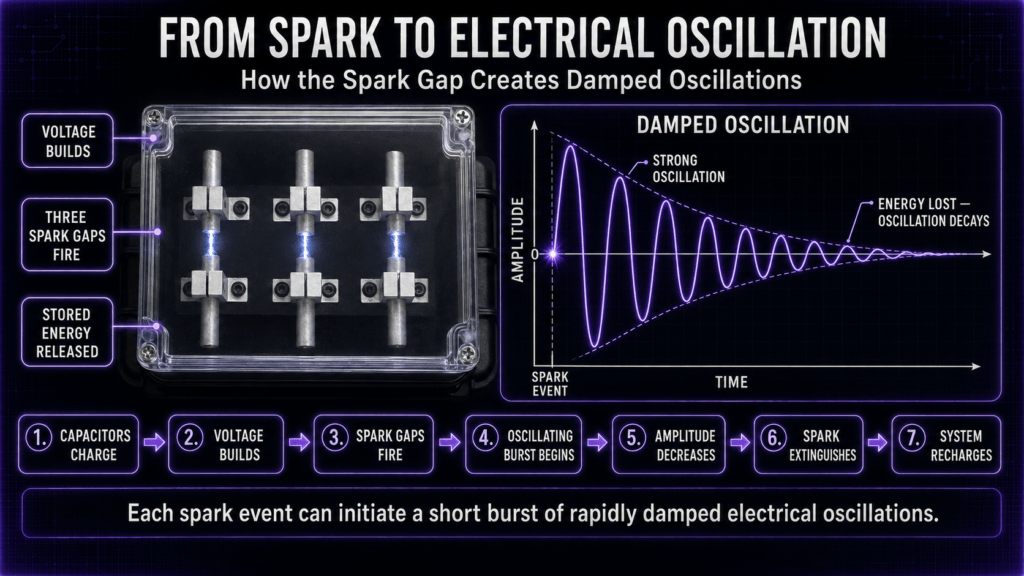
A graph of a damped oscillation resembles a wave whose peaks gradually become smaller until the oscillation disappears.
The spark-gap system can repeatedly supply new bursts of energy, producing repeated groups of rapidly damped high-frequency oscillations.
How Does a Spark Gap Start an Oscillation?
A spark gap consists of two conductive electrodes separated by a small air gap.
Under normal conditions, the air between the electrodes acts as an electrical insulator. As voltage rises, the electric field across the gap becomes stronger.
When the voltage becomes high enough to break down the air, the air becomes ionised and a conductive arc forms between the electrodes.
The spark gap has now changed very quickly from a poor conductor into a conductive path.
This sudden switching action allows stored energy to discharge through the surrounding circuit. The combination of capacitance and inductance causes the voltage and current to “ring,” producing a short burst of electrical oscillations.
As the available energy decreases, the oscillations become weaker and the arc extinguishes. The system can then recharge until the gap fires again.
The basic sequence is:
- Electrical energy enters the circuit.
- The capacitor network charges.
- Voltage builds across the spark gap.
- The air gap breaks down and an arc forms.
- Stored energy is released into the oscillating circuit.
- Voltage and current oscillate rapidly.
- Resistance and other losses reduce the oscillation.
- The arc extinguishes.
- Charging begins again.
This cycle can repeat many times each second while the generator is operating.
Spark Repetition Rate and Oscillation Frequency Are Not the Same
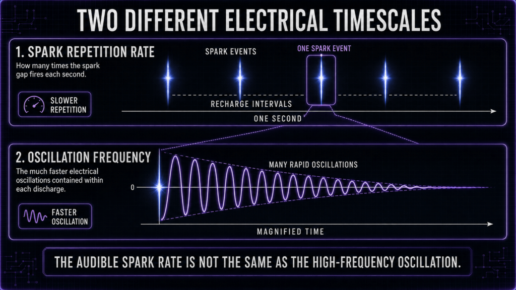
This is an important distinction.
The number of times the spark gap fires each second is the spark repetition rate.
The much faster rising, falling and reversing electrical activity within each discharge is the oscillation frequency.
One visible or audible spark event may contain a short train of numerous high-frequency oscillations. Therefore, counting sparks—or listening to the buzzing sound—does not reveal the full frequency content produced by the device.
A spark-gap circuit can also produce harmonics and a broad range of frequencies rather than one perfectly clean, stable frequency.
Its measured output will depend on factors including:
- Capacitance
- Circuit inductance
- Resistance and electrical losses
- Transformer and wiring characteristics
- Electrode condition
- Spark-gap behaviour
- Connected bulbs and other loads
- Measurement method and probe position
This is why the electrical activity from a traditional spark-gap generator can appear more complex on a spectrum analyser than the output from a modern single-frequency signal generator.
Why Are Electrical Oscillations Important?
Without rapidly changing electrical conditions, a traditional spark-gap plasma generator would not operate in the same way.
The oscillations are important because they:
- Create rapidly changing voltage and current
- Produce changing electric and magnetic fields
- Transfer energy through the high-frequency circuit
- Help energise and ionise the gas in the bulbs
- Contribute to the visible plasma effect
- Form part of the device’s characteristic spark-gap operation
The visible arc is therefore only one part of the process. The important electrical activity also includes the rapid oscillations generated during each discharge.
Key Point to Remember
An electrical oscillation is not simply “electricity moving quickly.”
It is a repeated change in voltage, current or charge.
In a traditional oscillating circuit, energy transfers between electric and magnetic fields. In a spark-gap system, the sudden discharge initiates short bursts of these rapidly changing electrical conditions.
Understanding that distinction provides the foundation for learning about frequency, resonance, tuned circuits and high-frequency plasma generation.
Here is Part 2, continuing directly from the first section.
Understanding Electrical Waveforms
In Part 1, we learned that electrical oscillations are repeated changes in voltage, current or electric charge.
One of the clearest ways to understand these changes is to represent them as a waveform.
A waveform is a graph showing how an electrical quantity changes over time. On a typical voltage waveform:
- The horizontal direction represents time.
- The vertical direction represents voltage.
- The centre line represents a chosen reference level, often zero volts.
- The shape of the line shows how the voltage rises, falls or reverses.
An oscilloscope displays electrical signals in this way, allowing engineers to observe details that happen far too quickly for the human eye to see.
A smooth, repeating waveform may appear as a regular wave. A spark-gap discharge, however, normally creates a much more complex pattern containing short bursts, sharp changes and damped oscillations.
Understanding these shapes helps answer the question: what are electrical oscillations actually doing inside a circuit?
What Is a Cycle?
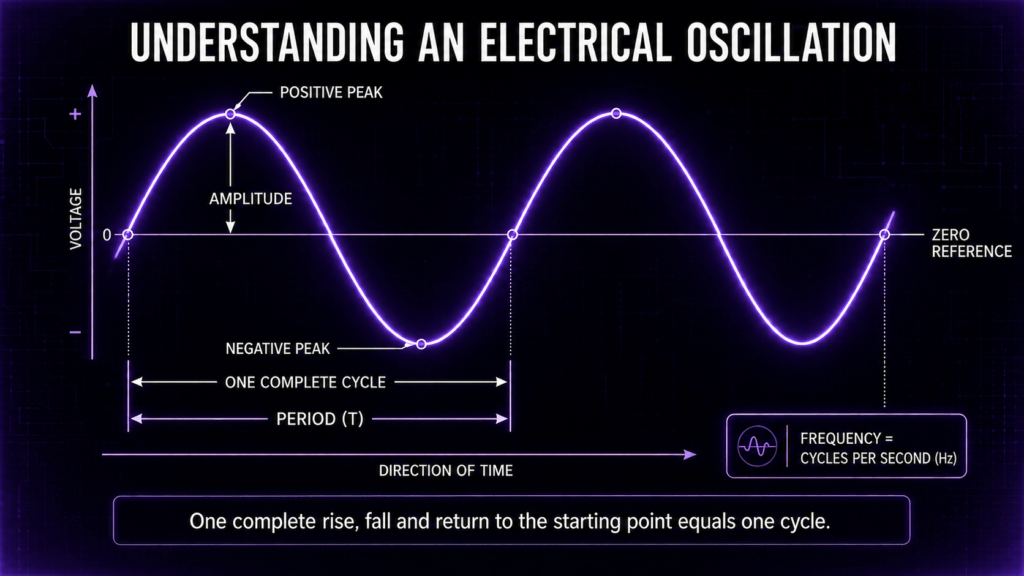
One complete repetition of an oscillation is called a cycle.
Imagine a voltage waveform beginning at zero. It rises to a positive peak, returns through zero, falls to a negative peak and then rises back to its starting point.
That complete journey is one cycle.
If the same pattern continues repeating, the circuit is producing a periodic electrical signal.
A cycle can therefore include:
- A rise in voltage
- A positive peak
- A return towards zero
- A negative change
- A negative peak
- A return to the starting point
Not every electrical oscillation forms a perfectly smooth wave, but the idea of a repeated cycle remains useful.
What Do Positive and Negative Voltage Mean?
Positive and negative voltage do not mean “good” and “bad” electricity.
They describe electrical potential relative to a chosen reference point.
If the voltage rises above the reference level, it is shown as positive. If it falls below the reference, it is shown as negative.
In an oscillating circuit, the voltage may repeatedly change polarity. This means the electrical potential across a component reverses during the cycle.
The current may also change direction.
This reversal is an important part of many oscillating circuits because it allows energy to move backwards and forwards between the circuit’s electric and magnetic fields.
In an ideal LC circuit:
- The capacitor begins charged with one polarity.
- It discharges and produces current.
- The current creates a magnetic field.
- The magnetic field then begins to collapse.
- The collapsing field helps keep current moving.
- The capacitor charges again with the opposite polarity.
- The process repeats in the other direction.
This alternating behaviour produces the electrical oscillation.
What Is Amplitude?
The amplitude describes the size or strength of a waveform relative to its central reference level.
On a voltage waveform, amplitude commonly refers to the voltage measured from the centre line to a peak.
For example, if a waveform reaches 100 volts above its reference level, its positive peak amplitude is 100 volts.
You may also see the term peak-to-peak voltage. This measures the entire distance between the highest positive point and the lowest negative point.
A waveform reaching:
- Positive 100 volts
- Negative 100 volts
would have a peak-to-peak value of 200 volts.
Amplitude and frequency describe different properties.
- Amplitude describes the size of the electrical change.
- Frequency describes how quickly the cycle repeats.
A high-amplitude signal is not necessarily a high-frequency signal, and a high-frequency signal is not necessarily high in amplitude.
It is therefore important not to use the words “frequency,” “power,” “voltage” and “intensity” as though they all mean the same thing.
What Is the Period of an Oscillation?
The period is the time required for one complete cycle.
It is normally represented by the letter T and measured in seconds.
If one complete oscillation takes one second, its period is one second.
If it takes one thousandth of a second, its period is one millisecond.
The shorter the period, the more cycles can fit into each second. Therefore, a shorter period corresponds to a higher frequency.
What Is Frequency?
Frequency tells us how many complete cycles occur every second.
It is measured in hertz, abbreviated as Hz.
For example:
- 1 Hz means one cycle per second.
- 50 Hz means 50 cycles per second.
- 1 kHz means 1,000 cycles per second.
- 100 kHz means 100,000 cycles per second.
- 1 MHz means 1,000,000 cycles per second.
Frequency and period are connected by the following relationship:
[
f=\frac{1}{T}
]
Here:
- (f) means frequency in hertz.
- (T) means the period in seconds.
For example, a frequency of 1,000 Hz has a period of:
[
T=\frac{1}{1000}=0.001\text{ seconds}
]
That is one millisecond per cycle.
Oscilloscope manufacturer Tektronix provides a useful beginner’s explanation of frequency, period, amplitude and waveforms.
What Is a Sine Wave?
A sine wave is a smooth, regular waveform often used to explain oscillating voltage and current.
It rises gradually to a positive peak, passes through zero, reaches a negative peak and then returns to its starting point.
Sine waves are useful because they represent a simple form of repetitive oscillation.
An ideal LC circuit can be mathematically described using sine and cosine waves. However, real electrical circuits are affected by resistance, component tolerances, connected loads, wiring, electromagnetic radiation and other losses.
For that reason, the electrical output from a practical spark-gap system should not be expected to look like one perfectly clean sine wave.
What Are Damped Electrical Oscillations?
A damped oscillation is an oscillation that gradually decreases in amplitude.
Imagine striking a bell.
The bell initially produces a strong sound, but the sound becomes progressively quieter because energy is being lost to the surrounding air and the bell’s material.
A similar process occurs in electrical circuits.
When a capacitor releases its stored energy into a circuit containing inductance, the voltage and current can oscillate. However, some of the energy is lost through:
- Electrical resistance
- Heat
- The spark itself
- Sound
- Electromagnetic radiation
- The connected load
- Losses within components and wiring
As energy leaves the oscillating circuit, the amplitude of each successive cycle becomes smaller.
On a graph, a damped electrical oscillation looks like a wave that starts strongly and gradually reduces towards zero.
OpenStax compares an RLC circuit with a damped mechanical oscillator because resistance causes electromagnetic energy to be dissipated as the oscillation continues. Read the OpenStax explanation of RLC oscillations.
Damped Oscillations in a Spark-Gap System
A traditional spark-gap generator can produce repeated bursts of damped oscillations.
The sequence is:
- The capacitor network charges.
- Voltage builds across the spark gap.
- The gap breaks down and becomes conductive.
- Stored energy is released into the circuit.
- Voltage and current oscillate rapidly.
- The oscillation loses energy and becomes weaker.
- The arc extinguishes.
- The capacitor begins charging again.
- The next spark initiates another burst.
Each spark event can therefore initiate a short group, or train, of high-frequency oscillations.
This is one reason the audible buzzing or visible firing of the spark gap should not be confused with the much faster electrical oscillation taking place within each discharge.
Continuous and Repeated-Burst Oscillations
Electrical oscillations can be sustained in different ways.
A modern electronic oscillator may receive a continuous energy supply that replaces the energy lost during each cycle. This can produce an almost continuous and stable waveform.
A spark-gap oscillator behaves differently.
Instead of creating one uninterrupted, perfectly smooth signal, it commonly produces repeated bursts. Each firing of the gap supplies another sudden pulse of energy to the oscillating circuit.
The result is better imagined as:
Charge → Spark → Oscillating burst → Decay → Recharge → Spark again
This repeated-burst operation contributes to the characteristic sound and complex frequency spectrum of traditional spark-gap equipment.
What Determines the Natural Oscillation Frequency?
Every LC circuit has a natural frequency determined primarily by its effective inductance and capacitance.
For an ideal LC circuit, the frequency is calculated using:
[
f_0=\frac{1}{2\pi\sqrt{LC}}
]
In this equation:
- (f_0) is the natural frequency in hertz.
- (L) is inductance in henries.
- (C) is capacitance in farads.
- (\pi) is approximately 3.1416.
The formula shows an important relationship:
- Increasing inductance lowers the natural frequency.
- Increasing capacitance lowers the natural frequency.
- Decreasing inductance raises the natural frequency.
- Decreasing capacitance raises the natural frequency.
OpenStax gives the corresponding angular-frequency relationship as:
[
\omega_0=\frac{1}{\sqrt{LC}}
]
The ordinary frequency in hertz is obtained by dividing angular frequency by (2\pi). See the OpenStax LC-circuit equations.
Real Circuits Are More Complicated Than the Formula
The LC formula describes an idealised circuit.
A working spark-gap plasma generator contains additional electrical properties, including:
- Transformer inductance
- Capacitor-bank capacitance
- Wiring inductance
- Stray or parasitic capacitance
- Contact resistance
- Spark-gap losses
- Bulb and cable loading
- Coupling between components
- Electromagnetic radiation
The actual oscillations are therefore determined by the complete system rather than by one component alone.
Different sections of the device may also show different frequency components depending on where and how a measurement is taken.
This means there may not be one single number that describes every aspect of the generator’s electrical output.
Does Changing the Spark Gap Change the Frequency?
Changing the spark-gap distance can alter the operation of the generator, but the effect needs to be described carefully.
A wider gap generally requires a higher voltage before the air breaks down. A narrower gap may fire at a lower voltage.
This can change:
- When the gap fires
- How frequently discharge events occur
- The energy available at the moment of firing
- The appearance and stability of the arc
- The sound of the generator
- The loading and damping of the oscillating circuit
However, the spark gap should not be treated as a simple frequency-control dial.
The principal ringing frequency of an ideal LC circuit is determined mainly by inductance and capacitance. Spark-gap adjustment can influence the complete operating behaviour, but it does not independently select a precise output frequency.
This distinction is important when explaining what electrical oscillations are and how a traditional plasma generator produces them.
Why Spark-Gap Waveforms Are Complex
A modern electronic signal generator can be designed to produce a clean sine wave at a precisely selected frequency.
A spark gap is a sudden electrical switching event.
Sudden transitions contain many frequency components. The discharge can excite the circuit’s natural oscillations while also producing harmonics, electrical noise and additional resonances.
The resulting signal may include:
- A main resonant frequency
- Harmonics
- Short transient pulses
- Damped oscillations
- Spark repetition components
- Frequencies created by other parts of the system
- Background electrical interference
This helps explain why a spectrum analyser may show several peaks rather than one perfectly isolated frequency.
Key Point to Remember
Electrical oscillations can be described using several separate properties:
- Waveform: the shape of the changing signal
- Amplitude: the size of the electrical change
- Period: the time required for one cycle
- Frequency: the number of cycles per second
- Damping: the gradual reduction in amplitude
- Natural frequency: the frequency at which an LC circuit tends to oscillate
In a spark-gap plasma generator, each visible discharge can initiate a much faster burst of damped electrical oscillations.
The spark repetition rate, oscillation frequency and complete frequency spectrum are connected, but they are not the same measurement.
Here is the final section of Lesson 10, including the plasma bulbs, resonance, measurement guidance, FAQs and conclusion.
How Electrical Oscillations Reach the Plasma Bulbs
The electrical oscillations produced within a spark-gap system must be transferred through the circuit before the bulbs can glow.
In my High Frequency Plasma Generator, the high-frequency producer, capacitor network, spark-gap assembly, connecting cables and two spiral plasma bulbs operate as parts of one complete electrical system.
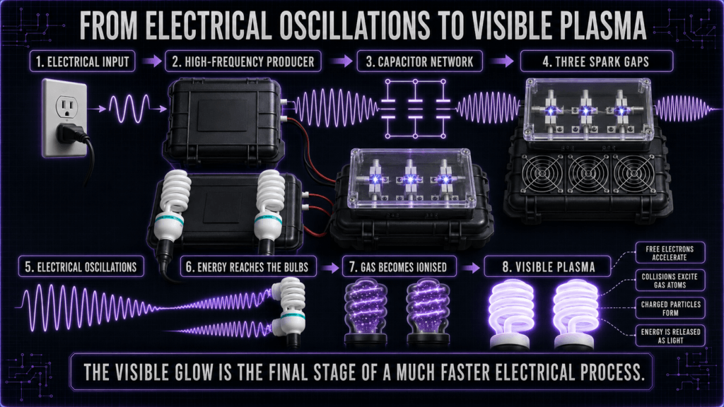
The simplified energy journey is:
Electrical input → High-frequency producer → Energy storage → Spark-gap discharge → Electrical oscillations → Plasma bulbs → Visible light
The visible light in the bulbs is therefore the final observable stage of a much faster electrical process.
Although the glow appears continuous to the human eye, the electrical conditions responsible for it may be changing extremely rapidly.
What Is Inside a Plasma Bulb?
The spiral bulbs contain low-pressure gas and vapour inside sealed glass tubing.
Under normal conditions, most of this gas is electrically neutral. Its atoms contain positively charged nuclei surrounded by negatively charged electrons.
When a sufficiently strong electrical field is applied, some free electrons inside the bulb gain energy and collide with the gas atoms.
These collisions can:
- Excite the atoms
- Remove electrons from some atoms
- Create additional free electrons
- Produce positively charged ions
- Allow electrical conduction through the gas
A gas containing free electrons, ions and neutral particles can be described as a plasma.
The exact amount of ionisation can vary. A gas does not need to have every atom ionised to display plasma behaviour. Many practical glow discharges are only partially ionised.
Research published by the National Institute of Standards and Technology explains that applying a sufficiently high electrical potential can cause a discharge gas to break down electrically, forming electrons and positively charged ions. Read the NIST explanation of radio-frequency glow discharge plasma.
How Does the Gas Begin to Glow?
The visible glow occurs because particles inside the gas absorb and release energy.
A simplified explanation is:
- The rapidly changing electric field accelerates free electrons.
- These electrons collide with gas atoms.
- Some atoms absorb energy and enter an excited state.
- The atoms later return to a lower-energy state.
- Energy is released as photons.
- Some of this energy becomes visible light.
In a fluorescent-style spiral bulb, the gas discharge can also produce ultraviolet radiation. The phosphor coating on the inside of the glass absorbs that ultraviolet energy and converts it into visible light.
This is why the outer spiral can glow brightly even though the main electrical process is taking place within the gas inside the tube.
Why Are Rapidly Changing Fields Important?
A static electrical field does not continually reverse.
An oscillating electrical field repeatedly changes in strength and direction. Charged particles inside the bulb respond to these changing conditions.
As the field changes, electrons can be accelerated, slowed and redirected. Collisions between these electrons and the gas atoms help sustain excitation and ionisation.
The rapidly changing electrical conditions therefore help:
- Initiate gas breakdown
- Move free electrons
- Produce collisions
- Excite gas atoms
- Maintain the discharge
- Create the visible glow
The plasma bulbs provide a clear visual indication that electrical energy is reaching the output stage of the generator.
However, brightness alone does not reveal the exact voltage, frequency, current or total energy in the circuit.
Do Electrical Oscillations Travel Through the Glass?
The glass envelope is an electrical insulator, but an electric field can act through an insulating material.
Depending on the bulb construction and electrical connections, energy can be coupled into the gas through conductive contacts, capacitance or rapidly changing electric fields.
This means that high-frequency electrical energy does not necessarily behave in the same way as low-frequency direct current travelling through an ordinary wire.
At higher frequencies, several effects become increasingly important:
- Capacitance between nearby conductive objects
- Inductance in wires and cables
- Changing electric and magnetic fields
- Coupling between circuit sections
- Electrical radiation
- The physical layout of the equipment
For this reason, the complete shape and arrangement of a high-frequency generator can influence its behaviour.
The Relationship Between Oscillations and Resonance
Electrical oscillations and resonance are closely connected, but they are not identical.
An oscillation is a repeated electrical change.
Resonance occurs when energy is supplied at, or near, a system’s natural frequency, allowing energy to build more effectively under suitable conditions.
A useful comparison is pushing a swing.
If each push arrives at approximately the right point in the swing’s movement, the swing rises higher. If the pushes arrive at unsuitable times, less energy is transferred into the motion.
Electrical resonance follows a related principle.
Capacitance and inductance give a circuit one or more natural frequencies. When electrical energy excites one of those frequencies, the corresponding oscillation may become more pronounced.
You can learn more about this relationship in Lesson 9 — What Is Resonance?.
Does the Whole Generator Have One Resonant Frequency?
It is tempting to describe a high-frequency generator as producing one exact frequency, but a practical spark-gap system is more complicated.
Different parts of the complete device contribute:
- Capacitance
- Inductance
- Resistance
- Coupling
- Loading
- Damping
- Stray electrical effects
The capacitor network and transformer may support particular oscillations. The connecting cables, spark-gap assembly and plasma bulbs can introduce additional electrical properties.
When the bulbs are connected, they become part of the electrical load. Their behaviour can influence the generator’s voltage, current, damping and frequency response.
The complete system may therefore contain:
- A principal oscillation
- Harmonics
- Spark-repetition components
- Short transient pulses
- Damped ringing
- Additional resonances
- Environmental electrical interference
This does not mean the device has no measurable frequencies. It means that any measurement must be explained in the context of the instrument, probe, position, settings and part of the device being observed.
How Can Electrical Oscillations Be Observed?
Electrical oscillations can be examined in two main ways:
Time-Domain Measurement
An oscilloscope displays voltage or current against time.
This can reveal:
- Waveform shape
- Peak amplitude
- Period
- Repetition rate
- Damping
- Pulses
- Transient events
A suitable oscilloscope may show the individual cycles within a burst, provided the instrument, probe, bandwidth and sampling rate are appropriate.
Frequency-Domain Measurement
A spectrum analyser displays signal strength across a range of frequencies.
Instead of showing how a signal changes moment by moment, it shows where energy is detected in the frequency spectrum.
This can reveal:
- Prominent frequency components
- Harmonics
- Broadband noise
- Repeated peaks
- Changes caused by distance or loading
The two instruments present different views of the same electrical activity.
An oscilloscope shows the shape of the signal over time. A spectrum analyser separates the detected signal into frequency components.
What Does a Pickup Coil Measure?
A small pickup coil or near-field probe can detect part of the changing electromagnetic field surrounding the generator.
This provides a useful form of indirect observation because the measuring instrument does not need to be electrically connected to the high-voltage output.
However, the reading depends strongly on:
- Distance from the generator
- Probe orientation
- Pickup-coil size and construction
- Cable length
- Instrument settings
- Nearby electrical equipment
- The precise measurement location
- Signal strength reaching the analyser input
Moving the pickup coil by only a small distance can change the displayed result.
A peak shown on a spectrum analyser therefore represents a frequency detected at that particular probe position and setup. It should not automatically be described as the device’s only output frequency.
It also does not, by itself, establish field strength at another location or demonstrate a biological or therapeutic effect.
Important High-Voltage Measurement Warning
Spark-gap plasma generators contain dangerous high voltage and fast electrical transients.
A standard oscilloscope probe, multimeter lead or spectrum-analyser cable must never be connected directly to the spark gap, plasma-bulb output or another high-voltage point unless the complete measurement system is specifically rated for the voltage, frequency, transient energy and circuit arrangement.
An incorrect connection could:
- Destroy the measuring instrument
- Cause electrical arcing
- Create a shock hazard
- Damage the plasma generator
- Place dangerous voltage on grounded equipment
- Produce misleading readings
Professional direct measurements require correctly rated high-voltage or high-voltage differential probes, suitable instruments and an operator who understands grounding, isolation, clearance distances and probe limitations.
Tektronix provides detailed guidance on the importance of using correctly rated equipment for safe high-voltage measurements.
Owners should not remove protective covers or attempt direct high-voltage measurements while the generator is connected to power.
Frequently Asked Questions
Are Electrical Oscillations the Same as Alternating Current?
They are closely related, but the terms are not always interchangeable.
Alternating current repeatedly changes direction and usually continues for as long as the AC source is operating.
An electrical oscillation can also be a short-lived transient, such as the damped ringing that follows a single switching or spark event.
A spark-gap circuit may therefore produce short oscillating bursts rather than one continuous AC waveform.
Does the Spark Gap Create the Frequency?
The spark gap acts as a fast electrical switch that releases stored energy and excites the oscillating circuit.
The principal ringing frequency is determined mainly by the effective inductance and capacitance of the circuit. The spark gap affects when the discharge begins, how the circuit is loaded and how the complete system behaves.
It is more accurate to say that the spark gap initiates or excites the oscillation rather than independently choosing one precise frequency.
Is the Buzzing Sound the High-Frequency Oscillation?
Not directly.
The audible sound is associated mainly with spark firing, mechanical vibration, airflow and lower-frequency repetition patterns.
The high-frequency electrical oscillations within each discharge can occur far faster than the human ear can hear.
Why Do the Bulbs Appear to Glow Continuously?
The discharges and electrical changes can repeat so rapidly that the human eye blends them into an apparently continuous glow.
Cameras may sometimes reveal flicker, banding or changes that are less obvious to the eye, depending on the shutter speed and frame rate.
Does a Brighter Bulb Mean a Higher Frequency?
Not necessarily.
Brightness can be affected by voltage, current, gas pressure, bulb construction, phosphor coating, coupling, distance, loading and many other factors.
Frequency is only one part of the complete electrical behaviour.
Are the Plasma Bulbs Producing the Oscillations?
The main oscillating activity originates within the generator’s electrical circuit.
The bulbs respond to the high-frequency energy and also act as part of the electrical load. Because the connected load affects the circuit, the bulbs can influence the system’s overall behaviour without being the original source of the oscillation.
Can a TinySA Measure the Generator’s Output?
A TinySA connected to a suitable pickup coil can detect some of the radio-frequency energy present around the operating generator.
It can help identify relative peaks and observe how the detected spectrum changes with distance or position.
However, it is not directly measuring every voltage and current inside the generator. The displayed results are influenced by the pickup coil, coupling, instrument range, input level and surrounding interference.
A TinySA must never be connected directly to the high-voltage output or spark-gap circuit.
Do Electrical Oscillations Continue After the Device Is Switched Off?
The active oscillations stop when the generator is disconnected from its energy source, although capacitors may retain dangerous stored charge for a period after disconnection.
The absence of visible sparks or glowing bulbs does not prove that every internal component is immediately safe to touch.
The enclosure should only be opened and maintained according to the supplied Owner’s Guide.
What Have We Learned?
Electrical oscillations are repeated changes in voltage, current or electric charge.
In a traditional spark-gap plasma generator:
- Electrical energy enters the device.
- The capacitor network stores energy.
- Voltage builds across the spark gap.
- The gap breaks down and an arc forms.
- Stored energy is released into the circuit.
- Capacitance and inductance produce rapidly changing voltage and current.
- Each oscillating burst loses energy and becomes damped.
- The spark extinguishes.
- The system recharges.
- The sequence begins again.
- High-frequency energy reaches the bulbs.
- Gas inside the bulbs becomes partially ionised and produces visible light.
The visible plasma is therefore the final result of a chain of electrical events happening throughout the generator.
Conclusion
So, what are electrical oscillations?
They are repeated changes in electrical conditions that allow energy to move between electric and magnetic fields.
In a spark-gap plasma system, the sudden discharge of stored electrical energy can excite short bursts of high-frequency oscillation. These oscillations travel through the complete circuit and help create the changing fields that energise the gas inside the plasma bulbs.
Understanding electrical oscillations also helps explain:
- Why capacitors are used
- What the spark gap does
- Why circuit inductance matters
- How resonance can occur
- Why the bulbs glow
- Why several frequencies may be detected
- Why spark repetition rate is not the same as oscillation frequency
Electrical oscillations are one of the central principles connecting the capacitor bank, spark gap, transformer, wiring and plasma bulbs into one working high-frequency system.
📘 Lesson 10 of 24 — Complete
Previous lesson: Lesson 9 — What Is Resonance?
Next lesson: Lesson 11 — Coming Soon
Educational and Safety Disclaimer
This lesson is provided for general education only.
High-frequency plasma generators contain potentially lethal voltages, stored electrical energy and rapidly changing electromagnetic fields. Do not open, modify, probe or service the generator while it is connected to power. Follow the supplied operating and maintenance instructions.
The High Frequency Plasma Generator is not a medical device and is not intended to diagnose, treat, cure, mitigate or prevent any disease or medical condition.
This completes the full Lesson 10 article at approximately 2,500–3,000 words across all three parts.