
Lesson 24 of 24 — High Frequency Plasma Learning Centre
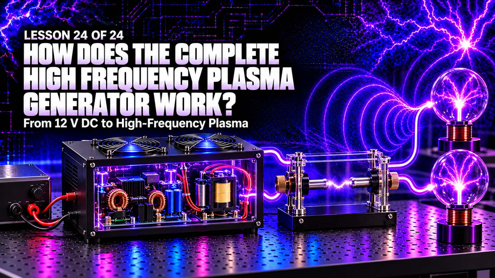
The High Frequency Plasma generator is not one component but a sequence of energy conversions. A regulated supply changes mains electricity into 12 V DC. A ZVS driver turns that DC into rapidly alternating current. A flyback transformer raises the voltage, capacitor sections accumulate energy, an adjustable zinc spark gap releases it in short pulses, and an oscillatory output excites two plasma bulbs.
Every stage has a different job. The supply provides energy, the driver controls magnetic switching, the flyback creates high voltage, the capacitors store charge, the spark gap acts as a fast threshold switch and the output network rings at high frequency.
This final lesson explains how the complete High Frequency Plasma generator works, how the stages interact, what determines its behaviour and why safe construction, enclosure and measurement are essential.
What You’ll Learn
By the end of this lesson, you will understand:
- the complete energy path through the generator;
- why 12 V DC must be switched before entering the flyback;
- how the balanced ZVS primary creates changing magnetic flux;
- how the flyback charges the capacitor sections;
- why capacitor energy rises with the square of voltage;
- how the zinc spark gap becomes a self-triggering switch;
- how capacitance and inductance create damped high-frequency ringing;
- why the plasma bulbs glow;
- which components affect switching, spark repetition and output resonance;
- how losses, loading and parasitic effects change real operation;
- and what the complete system can and cannot demonstrate.
The Complete Generator in One Line
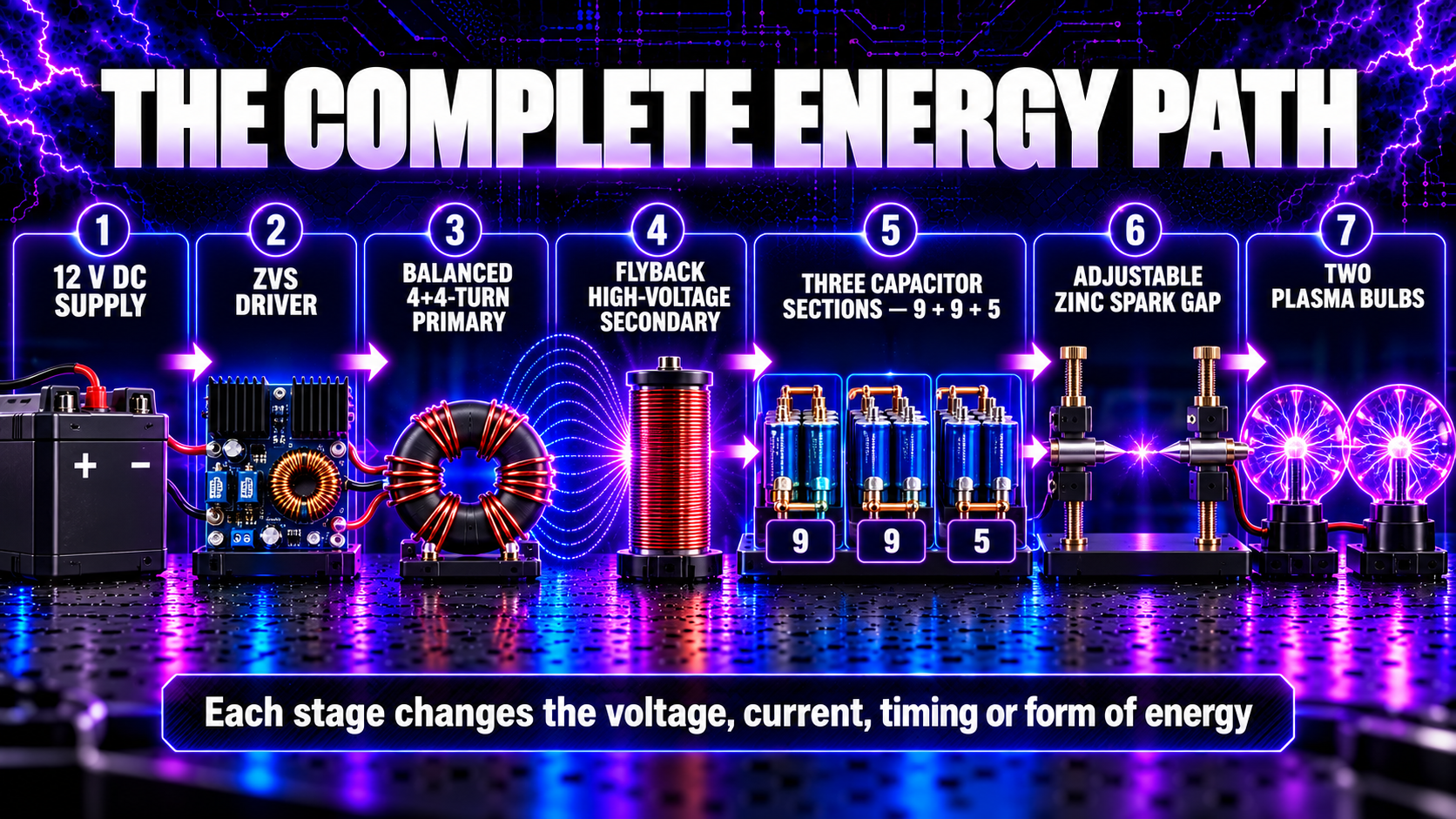
The working chain is:
Mains input → regulated 12 V DC supply → ZVS driver → balanced 4+4-turn flyback primary → flyback high-voltage secondary → capacitor sections → adjustable zinc-rod spark gap → output network → two plasma bulbs
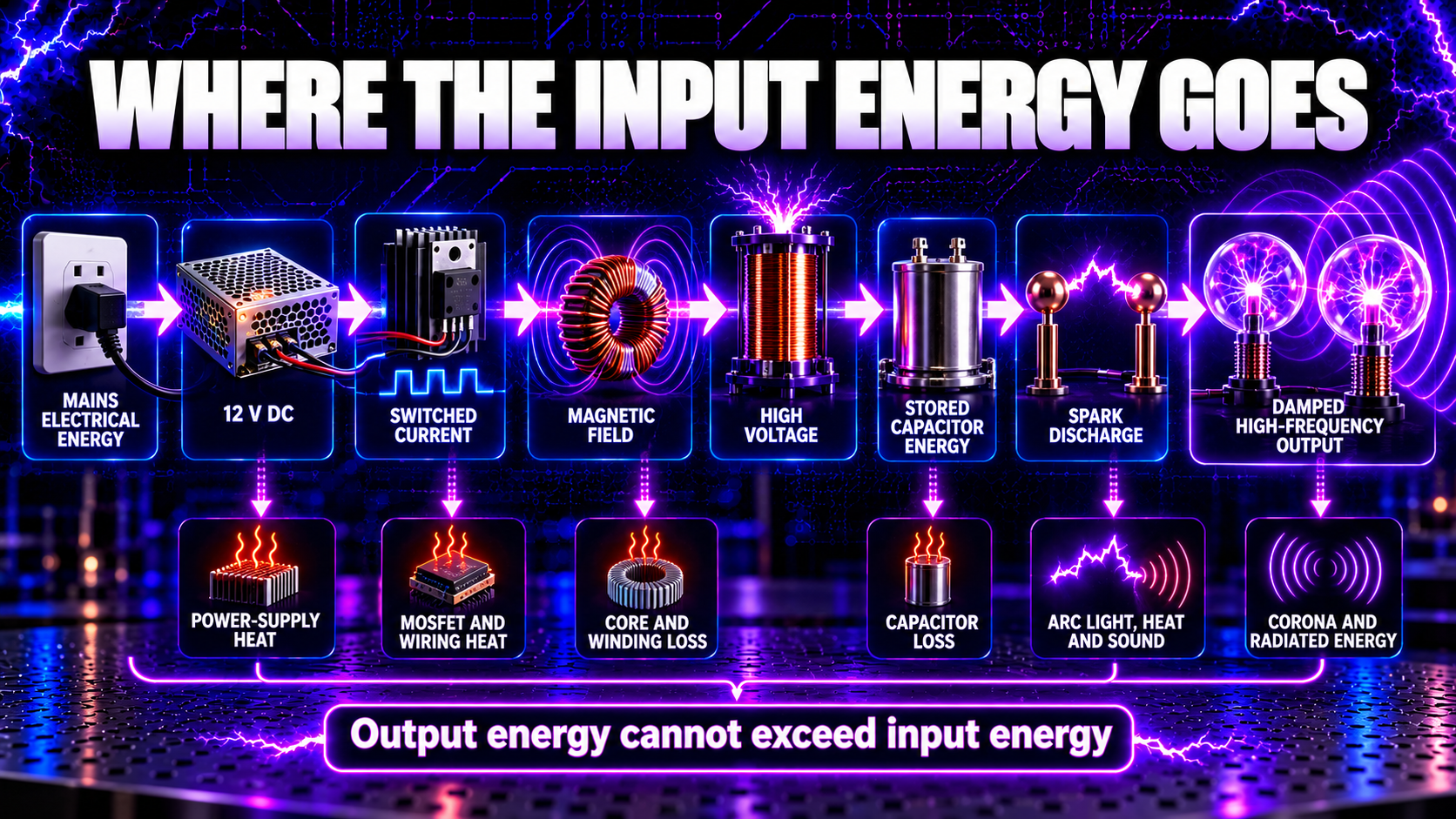
Energy moves through several forms:
- mains-frequency electrical energy;
- regulated low-voltage DC;
- high-frequency switched current;
- changing magnetic-field energy;
- high-voltage electrical energy;
- electrostatic energy stored in capacitors;
- a rapid spark-discharge pulse;
- damped high-frequency oscillation, electric fields, light, heat and sound.
The device does not create energy. Output energy must come from the input, and some is inevitably lost in the supply, MOSFETs, wiring, transformer, capacitors, arc and bulbs.
Stage 1: The 12 V DC Power Supply
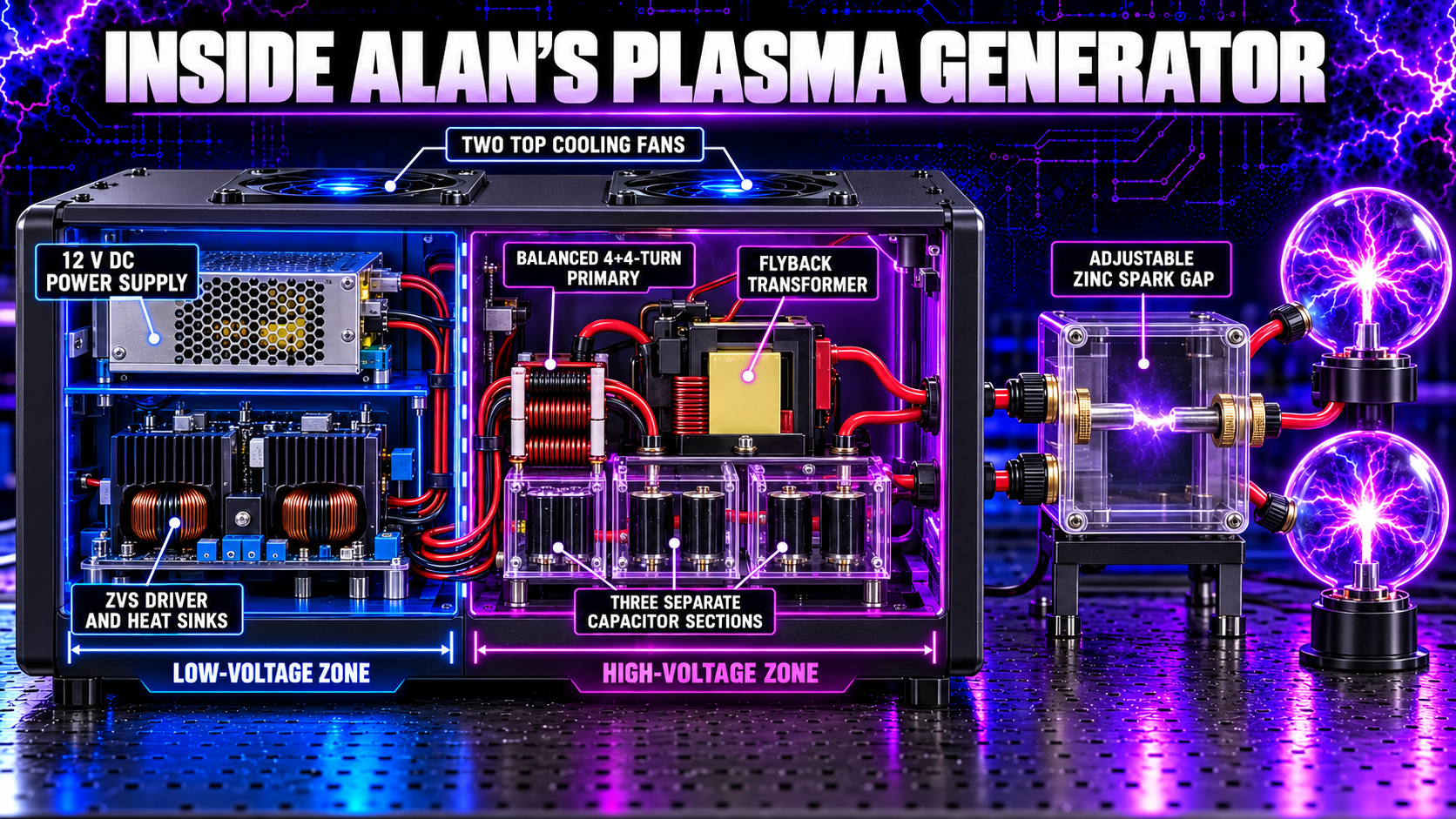
The regulated power supply is the generator’s energy source. In Alan’s established design, it provides 12 V DC with current capacity suitable for the ZVS stage. This is a relatively low voltage, but the available current is substantial and can overheat wiring or components if a fault occurs.
The supply performs three important jobs:
- isolates and converts the incoming mains supply;
- holds the low-voltage output near its intended value as the load changes;
- and provides current for the driver, flyback and subsequent charging process.
A fuse or protective device must suit the cable, switch, connector and expected current—not merely the largest current the supply can deliver. Secure terminations, correct polarity and adequate conductor size reduce resistive heating.
Disconnecting the 12 V supply stops new energy entering the system, but it does not guarantee that the capacitor sections are discharged.
Stage 2: The ZVS Driver
Steady DC cannot continuously operate a transformer because it does not provide continuously changing magnetic flux. The ZVS driver solves this problem by making current alternate through the added flyback primary.
ZVS means zero-voltage switching. In a resonant driver, inductance and capacitance shape the switching transition so that a MOSFET can turn on when the voltage across it is near zero. This can reduce transition loss and heating compared with hard switching.
It does not mean that the circuit contains zero voltage, generates no heat or is inherently safe.
The two MOSFET paths self-oscillate and alternately energise the two halves of a centre-tapped primary. Resonant behaviour depends on inductance, capacitance, supply voltage, load and component tolerances. If the flyback or output load changes, the ZVS operating point can also change.
The driver’s heat sinks and forced airflow remove losses that appear as heat. Fans do not correct an overloaded or unbalanced circuit; they only help keep a correctly operating circuit within a reasonable temperature range.
Stage 3: The Balanced 4+4-Turn Primary
The ZVS output connects to two equal, tightly wound sections around the exposed flyback core. Alan’s successful build uses four turns on each side of the centre tap.
Balance matters. If one half has fewer turns, sits farther from the core or is wound loosely, its inductance and coupling differ. The corresponding MOSFET may carry greater current, switch at the wrong point or overheat.
The two sections create magnetic flux in alternating directions. Because the ferrite core links the primary with the original high-turn secondary, changing flux induces a voltage in that secondary.
The added primary is physically separate from the secondary. Energy crosses the insulation boundary through the electromagnetic field. Stray capacitance can still couple high-frequency current, so galvanic separation must never be treated as permission to touch the secondary.
Stage 4: The Flyback Raises the Voltage
The television-style flyback contains many secondary turns and insulation designed for high voltage. The changing primary field produces a much larger secondary voltage with far lower available current than on the 12 V side.
A classic flyback converter stores magnetic energy during switch-on and delivers it during switch-off. Alan’s self-oscillating resonant driver is not identical to a textbook single-switch converter, but it still relies on primary inductance, magnetic coupling, winding polarity and rapid flux change.
Real output depends on more than turns ratio. Important variables include:
- primary inductance and winding position;
- switching waveform and frequency;
- ferrite core condition and gap;
- secondary resistance and internal rectification;
- leakage inductance and parasitic capacitance;
- supply voltage and current capability;
- capacitor-bank loading;
- and unintended corona or arcing.
This is why a flyback’s output cannot be predicted safely from primary and secondary turns alone.
Stage 5: The Capacitor Sections Store Energy
The flyback output charges the high-voltage capacitor network. In the current design, 23 polypropylene film capacitors are arranged as distinct sections: two groups of nine and one group of five. Their intended separation and interconnection form part of the circuit; accidentally joining sections changes the electrical behaviour.
For a capacitor with capacitance \(C\) charged to voltage \(V\), stored energy is:\[ E=\frac{1}{2}CV^2 \]
Voltage is squared. Doubling voltage stores four times the energy in the same capacitance. This is why a physically small capacitor network can become dangerous at high voltage.
The network also influences the output’s resonant behaviour. Series and parallel connections alter effective capacitance and voltage distribution. Lead length, solder joints, board tracks and spacing add resistance and inductance that become significant during fast pulses.
Capacitors can remain charged after the generator is switched off. A designed discharge path is required; an arc having stopped is not proof that the network is safe.
Stage 6: The Adjustable Zinc Spark Gap
The spark gap is a voltage-controlled switch with no mechanical trigger. While the capacitor sections charge, air between the two zinc rods normally acts as an insulator.
As voltage rises, the electric field across the gap strengthens. At breakdown, free electrons accelerate and collide with air molecules, creating more charged particles. A conductive plasma channel forms rapidly and the gap’s impedance falls.
The stored capacitor energy now has a discharge path. Current rises quickly, voltage collapses, the arc can no longer sustain itself and the gap returns to its insulating state. Charging then begins again.
Gap distance affects breakdown voltage and repetition behaviour. A wider gap generally needs a stronger electric field to fire, but electrode shape, erosion, contamination, pressure, humidity and airflow also matter.
Zinc rods are sacrificial. Repeated arcs heat, pit and erode their tips. The adjustable holders allow the working gap to be restored as the rods wear. Cleaning and adjustment must be performed only after isolation, discharge and verification that the equipment is dead.
Stage 7: The Discharge Produces High-Frequency Ringing
When the gap fires, the capacitor network and circuit inductance form a rapidly changing RLC system. Energy moves between the capacitors’ electric field and the inductive magnetic field.
For an idealised LC circuit, the resonant frequency is:\[ f_0=\frac{1}{2\pi\sqrt{LC}} \]
Resistance removes energy on every cycle, so the real waveform decays. The result is a damped oscillation rather than a permanent sine wave.
The generator is distributed rather than ideal. Output cables, bulb electrodes, capacitor leads, transformer windings, connections and nearby objects all contribute inductance and capacitance. The spark is a fast, non-linear event, so it also creates harmonics and broadband energy.
The output therefore contains more than one frequency. It includes ZVS switching components, the slower spark repetition rate, resonant ringing modes and harmonics generated by rapid transitions.
Stage 8: The Two Plasma Bulbs Glow
The output network connects to two sealed bulbs containing low-pressure gas. A sufficiently strong alternating electric field accelerates electrons inside the bulbs. Collisions ionise or excite gas atoms, creating a visible plasma discharge.
Excited atoms and ions release photons as they return towards lower-energy states. Gas composition, pressure, bulb geometry, electrode arrangement, voltage and waveform influence colour and filament pattern.
The bulbs are visible loads on the resonant system. Connecting, removing or changing them can alter capacitance, loading and field distribution, so the generator may not behave identically with a different bulb arrangement.
The glow shows that the gas is being excited. It does not by itself measure output power, frequency, biological effect or medical benefit.
One Complete Operating Cycle
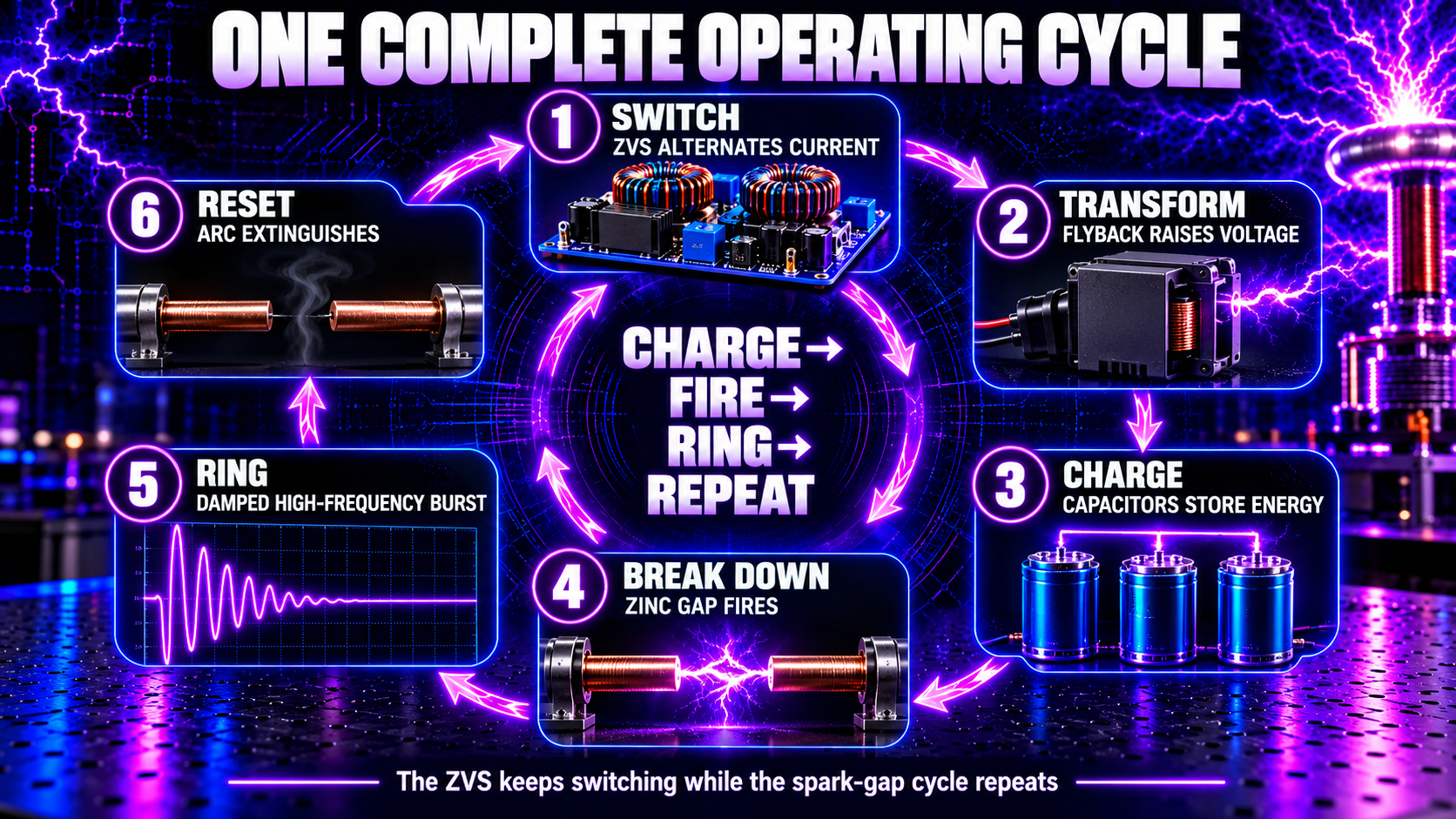
Although the ZVS driver oscillates continuously while powered, the spark-gap output repeats a charge-and-release cycle:
- Switch: the ZVS driver alternates primary current.
- Transform: changing core flux produces high voltage in the flyback secondary.
- Charge: high-voltage pulses add energy to the capacitor sections.
- Reach threshold: the electric field across the zinc gap rises.
- Break down: air ionises and a conductive channel forms.
- Discharge: stored capacitor energy enters the output network.
- Ring: capacitance and inductance exchange energy in a decaying burst.
- Extinguish: losses reduce current until the spark stops.
- Reset: the gap becomes insulating and the capacitors begin charging again.
Hundreds or thousands of ZVS switching events may contribute to charging between spark events, depending on the actual operating conditions. The rates must be measured rather than assumed.
What Controls the Generator’s Behaviour?
Different adjustments influence different stages:
| Variable | Main effect |
|---|---|
| Supply voltage and current limit | Available input power and charging rate |
| ZVS tank components | Switching behaviour and MOSFET conditions |
| Primary turns and tightness | Inductance, coupling and core flux |
| Flyback construction | Voltage transformation, rectification and losses |
| Effective capacitance | Stored energy and resonant behaviour |
| Circuit and cable inductance | Ringing frequency and pulse shape |
| Spark-gap distance | Breakdown threshold and repetition behaviour |
| Zinc-rod condition | Arc stability and gap consistency |
| Bulbs and nearby objects | Output loading and electric-field distribution |
| Temperature and airflow | Losses, reliability and operating drift |
Changing one part can affect several stages. For example, widening the spark gap may raise the firing threshold, increase capacitor voltage before discharge, reduce firing rate and increase insulation stress.
Where Does the Input Energy Go?
Only part of the input becomes useful oscillatory output. Energy is also lost through:
- power-supply inefficiency;
- MOSFET conduction and switching loss;
- winding resistance and ferrite-core loss;
- capacitor equivalent series resistance;
- spark light, heat, sound and electrode erosion;
- corona and leakage current;
- electromagnetic radiation;
- and heating in connections and bulbs.
These losses explain why the device requires ventilation and why output power must be lower than input power. A brighter arc or louder gap is not automatically evidence of better electrical efficiency.
How Is the Complete System Measured?
No single instrument describes the entire generator.
The 12 V input can be monitored with a correctly installed DC ammeter and voltage measurement. ZVS behaviour is best investigated on the low-voltage side using suitably isolated voltage or current probes. Temperature measurements can reveal abnormal heating.
The high-voltage and spark output should usually be examined non-contact with a pickup loop, antenna, optical sensor or other suitably isolated method. A tinySA can compare emitted frequency spectra when probe distance, orientation, attenuation, span and collection time remain fixed.
The established comparison method—25 cm probe distance and 30 seconds of MAX HOLD—can show whether peaks change between tests. It does not provide a calibrated measurement of field strength and must not be interpreted as proof of a biological effect.
Never connect an ordinary multimeter, oscilloscope probe or tinySA input directly to the flyback, capacitor, spark-gap or bulb wiring.
Typical Symptoms and What They Suggest
No activity
Check low-voltage supply output, fuse, switch, connectors, ZVS input polarity, fan operation and winding continuity with power isolated.
High supply current with weak output
Possible causes include an incorrect primary winding, saturation, shorted turns, a failed MOSFET, unintended arcing or excessive loading.
One MOSFET or heat sink runs hotter
This may indicate unequal primary turns, loose winding placement, mismatched components or asymmetric switching.
Intermittent output
Inspect for damaged connections, capacitor joints, contaminated spark-gap surfaces, drifting gap distance, overheating and insulation tracking.
Hissing or ozone away from the intended gap
This suggests corona or insulation breakdown. Stop operation and locate the unintended discharge before reuse.
Troubleshooting must begin with isolation and safe discharge. A fault is not permission to bypass covers, interlocks, fuses or grounding.
What the Generator Can—and Cannot—Show
The generator visibly demonstrates transformer action, resonance, capacitance, inductance, gas ionisation, electrical breakdown and electromagnetic coupling. Spectrum measurements can show a complex mixture of switching components, ringing modes and broadband emissions.
Those observations do not establish that every detected frequency reaches a person with equal strength, nor that a spectrum peak has a particular health effect. Electrical measurements describe the machine; medical claims require appropriate biological evidence and regulated clinical evaluation.
The High Frequency Plasma generator is an educational and experimental high-frequency device. It is not medical equipment and is not intended to diagnose, treat, cure or prevent disease.
Frequently Asked Questions
Does the generator create one frequency?
No. It produces ZVS switching components, spark repetition, damped resonant ringing, harmonics and broadband energy.
Why are there two capacitor charging and discharge timescales?
The flyback charges the capacitor sections over many switching cycles. The spark releases stored energy much more rapidly.
Does ZVS make the whole machine cool?
No. ZVS can reduce MOSFET transition losses, but conduction, core, winding, capacitor and arc losses still produce heat.
Why must the two primary halves be equal?
Equal turns and similar placement help the two switching paths see comparable inductance and coupling.
Does a wider spark gap always improve output?
No. It changes firing threshold, repetition, energy per event and component stress. Too wide a gap may prevent reliable firing or cause unintended flashover elsewhere.
Can the output voltage be calculated from turns ratio?
Not reliably on its own. Resonant waveforms, load, internal rectification, leakage and parasitic effects also matter.
Why do the bulbs change the circuit?
Their electrodes, gas discharge and connecting cables add capacitance and loading to the resonant output.
Is the circuit safe after switching off?
Not until all energy sources are isolated, stored charge is discharged through a designed system and the circuit is proved dead with suitable equipment.
Complete-System Safety
The combination of mains input, high current, high voltage, spark discharge and stored capacitor energy can cause fatal electric shock, burns, fire, component rupture and electromagnetic interference.
The equipment should use a closed enclosure, secure mains earth where required, suitable fusing, guarded high-voltage terminals, strain relief, adequate creepage and clearance, ventilation and a designed discharge system. Access to hazardous sections should be prevented during operation.
Before inspection or adjustment:
- switch off and disconnect every energy source;
- prevent accidental reconnection;
- wait for the designed discharge process;
- discharge stored energy using the intended method;
- prove the relevant conductors dead with correctly rated equipment.
Keep the generator away from TVs, laptops, computers, phones and other sensitive electronics. Do not use it if pregnant or with a pacemaker or other implanted electronic device.
Construction, live testing and repairs must be undertaken only by a competent person familiar with high-voltage and high-frequency hazards.
What Have We Learned?
The complete generator is a chain of controlled energy conversions. The 12 V supply feeds a resonant ZVS driver. Its balanced 4+4-turn primary changes magnetic flux in the flyback. The secondary produces high voltage that charges distinct capacitor sections. The zinc spark gap fires at a threshold and releases that stored energy into an RLC output network. The resulting damped high-frequency bursts excite gas inside two plasma bulbs.
Understanding the machine means keeping its timescales separate: continuous ZVS switching, slower capacitor charging and spark repetition, and very fast ringing within each discharge.
🧠 Final Key Takeaways
- The generator transforms energy; it does not create it.
- DC must be switched to produce changing magnetic flux.
- ZVS reduces switching-transition loss but does not remove voltage or heat.
- Tight, equal 4+4-turn primary sections support balanced operation.
- The flyback raises voltage and charges the capacitor network.
- Capacitor energy increases with the square of voltage.
- The zinc spark gap is a self-triggering threshold switch.
- Each discharge initiates damped RLC ringing.
- Switching rate, spark repetition and ringing frequency are different.
- The two plasma bulbs are electrical loads that alter the output network.
- Spectrum measurements describe emissions, not medical effects.
- Capacitors may remain dangerous after the supply is disconnected.
Your 24-Lesson Learning Journey Is Complete
You have progressed from the meaning of plasma, frequency, resonance and ionisation to capacitance, inductance, transformers, flybacks, measurement and the operation of the complete generator.
Previous Lesson: Lesson 23 — How Are High Frequencies Measured?
Return to the High Frequency Plasma Learning Centre to revisit any lesson.
Further Reading
- Texas Instruments — Zero Voltage Switching Resonant Power Conversion
- Texas Instruments — Flyback Converter Operation
- OpenStax — Energy Stored in a Capacitor
- OpenStax — Resonance in an AC Circuit
- UK HSE — Electrical safety frequently asked questions
Join the High Frequency Plasma Community
Join Alan and other owners in the free Telegram group for general discussion and shared experiences:
Disclaimer
This lesson is for general educational purposes. The High Frequency Plasma generator is not medical equipment and is not intended to diagnose, treat, cure or prevent any disease or health condition.
High-voltage transformers, spark gaps and charged capacitors can cause fatal electric shock, severe burns, fire, component rupture and electromagnetic interference. Do not construct, open, modify, probe or repair the equipment unless you are competent and use suitable enclosures, isolation, interlocks, discharge systems and correctly rated instruments.
🎉 Learning Centre Complete
You now understand the principles behind every major stage of the High Frequency Plasma generator—from the 12 V supply to the two glowing plasma bulbs.
The complete 24-lesson Learning Centre can now serve as a reference for owners, builders and readers who want to understand the electrical science behind Alan’s handcrafted system.