
Lesson 20 of 24 — High Frequency Plasma Learning Centre
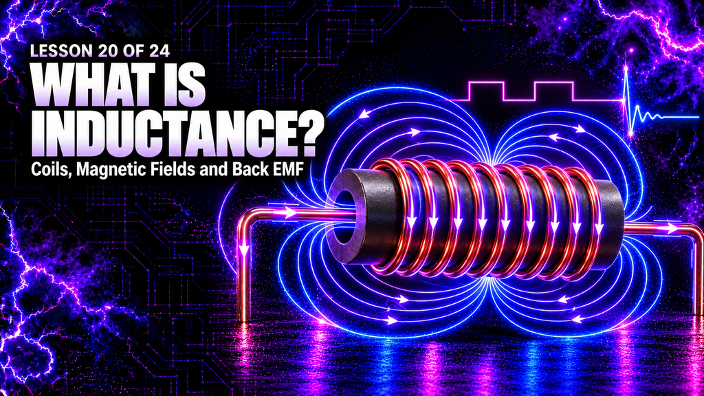
Inductance is the electrical property that links changing current with magnetic flux and an induced voltage. Every current-carrying conductor has some inductance, but winding the conductor into a coil—and often adding a magnetic core—can make the effect much stronger.
Lesson 20 of 24 — High Frequency Plasma Learning Centre
Inductance is central to transformers, motors, relays, filters, power converters, radio circuits and spark-gap systems. In the High Frequency Plasma generator, it appears in the ZVS driver, the flyback transformer, connecting wires and output network. Together with capacitance, it helps determine how energy oscillates and which frequencies are produced.
This lesson explains what inductance is, why an inductor opposes changes in current, how energy is stored in a magnetic field, what a henry means, how inductance behaves with DC and AC, and how it works throughout the plasma generator.
What You’ll Learn
By the end of this lesson, you will understand:
- what inductance means;
- how changing current creates an induced voltage;
- the equation \(V_L=-L\,dI/dt\);
- why inductance is measured in henries;
- how an inductor stores magnetic-field energy;
- what determines a coil’s inductance;
- the difference between self-inductance and mutual inductance;
- how inductors behave with DC, AC and pulses;
- what inductive reactance and the RL time constant mean;
- how inductance and capacitance create resonance;
- and how inductance works in the ZVS driver, flyback and spark-gap output.
The Short Answer: What Is Inductance?
Inductance is a circuit’s tendency to produce a voltage when its current changes.
A current produces a magnetic field. If the current changes, the magnetic field and magnetic flux also change. Faraday’s law tells us that this changing flux induces an electromotive force, or emf.
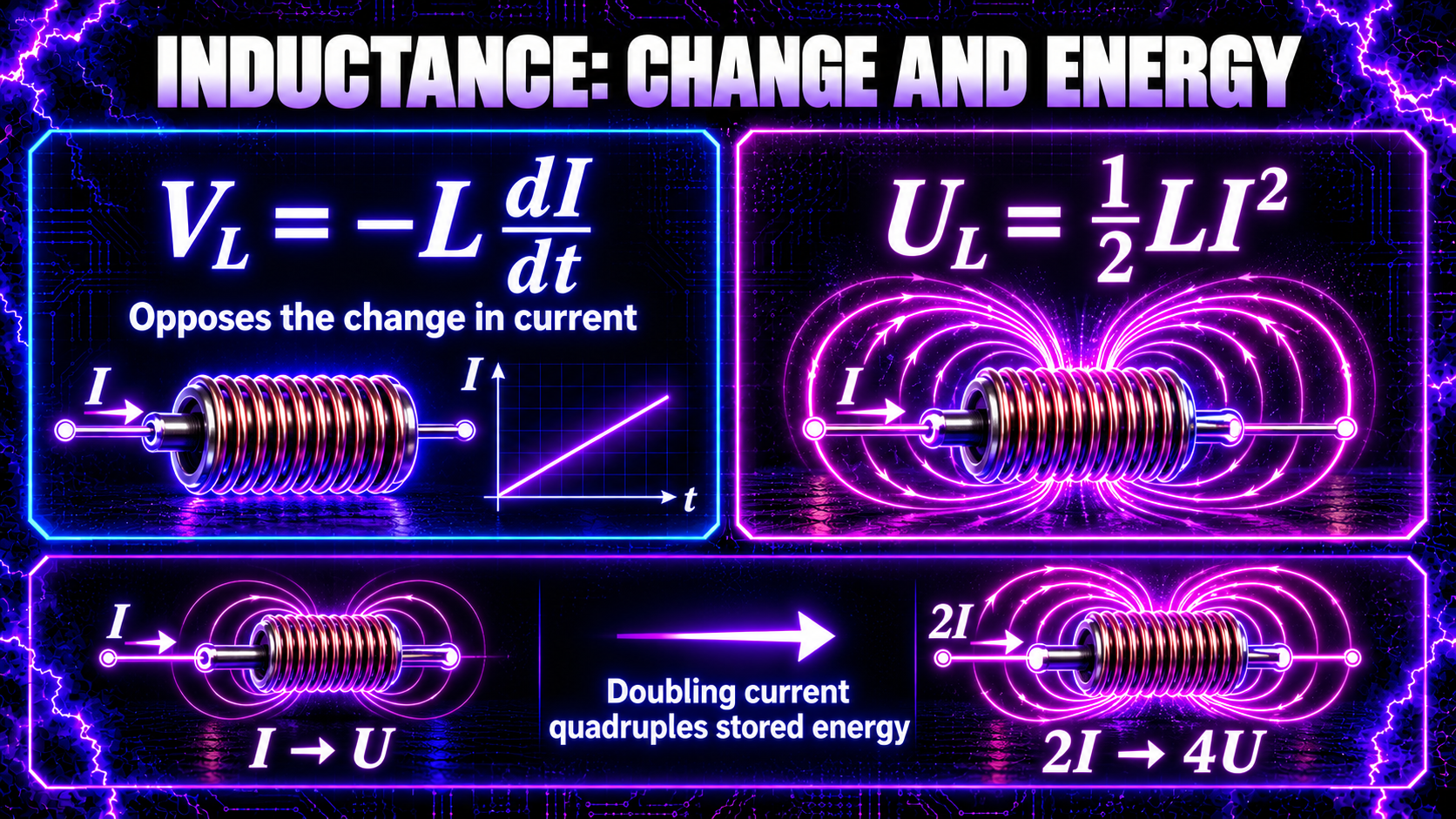
For an ideal inductor:\[ V_L=-L\frac{dI}{dt} \]
where:
- \(V_L\) is the induced voltage;
- \(L\) is inductance;
- \(dI/dt\) is the rate at which current changes;
- and the minus sign represents Lenz’s law.
Lenz’s law means the induced voltage acts in a direction that opposes the change in current. An inductor does not oppose current simply because current exists. It opposes current increasing or decreasing.
What Is an Inductor?
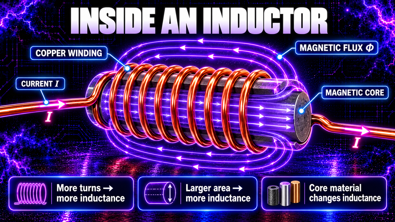
An inductor is a component designed to provide inductance. The simplest form is a coil of insulated wire.
When current flows through the coil, a magnetic field forms around each turn. The fields combine, producing concentrated magnetic flux through the centre of the coil. A core made from ferrite, powdered iron, laminated steel or another magnetic material can guide and strengthen that flux.
Common inductor forms include:
- air-core coils;
- ferrite-core inductors;
- iron-powder toroids;
- chokes for filtering interference;
- transformer windings;
- and the unavoidable inductance of wires, tracks and component leads.
The circuit symbol shows a series of curved loops. Real inductors also contain wire resistance, inter-turn capacitance, core loss and limits on current and frequency.
What Is a Henry?
The SI unit of inductance is the henry, symbol H.
One henry produces an induced voltage of one volt when current changes at one ampere per second:\[ 1\ \text{H}=1\ \text{V·s/A}=1\ \Omega\text{·s} \]
Many practical components use smaller units:
| Unit | Symbol | Value in henries |
|---|---|---|
| Henry | H | \(1\ \text{H}\) |
| Millihenry | mH | \(10^{-3}\ \text{H}\) |
| Microhenry | µH | \(10^{-6}\ \text{H}\) |
| Nanohenry | nH | \(10^{-9}\ \text{H}\) |
Even a short straight wire has inductance. At low frequency it may be negligible; during a very fast current pulse, it can produce substantial voltage.
Why Does an Inductor Oppose a Change in Current?
When current starts rising, the growing magnetic field induces a voltage that opposes that rise. The current therefore cannot jump instantly from zero to a large value in an ideal inductor.
When the source is removed, the magnetic field begins collapsing. The induced voltage reverses polarity in an attempt to keep current flowing in the same direction. If no safe path exists, the voltage can rise high enough to arc across a switch or damage a semiconductor.
This turn-off voltage is sometimes called inductive kickback or back emf. It is not free energy. It is the release of energy previously stored in the magnetic field.
Protection methods can include flyback diodes, snubbers, transient suppressors or deliberately designed resonant paths. The correct method depends on whether the circuit is DC, AC, high-frequency or intended to generate high-voltage pulses.
How Much Energy Does an Inductor Store?
An ideal inductor stores energy in its magnetic field:\[ U_L=\frac{1}{2}LI^2 \]
This shows that stored energy depends on inductance and on the square of current.
- doubling inductance doubles the energy at the same current;
- doubling current produces four times the energy at the same inductance.
Capacitors and inductors are complementary:
- a capacitor stores energy in an electric field: \(U_C=\tfrac12CV^2\);
- an inductor stores energy in a magnetic field: \(U_L=\tfrac12LI^2\).
That relationship becomes crucial in resonant and spark-gap circuits, where energy can move repeatedly between capacitance and inductance.
What Determines a Coil’s Inductance?
For an ideal long solenoid, the approximate relationship is:\[ L\approx\mu\frac{N^2A}{\ell} \]
where \(N\) is the number of turns, \(A\) is coil cross-sectional area, \(\ell\) is magnetic-path length and \(\mu\) represents the permeability of the core region.
This gives useful design rules:
- more turns usually increase inductance strongly because of the \(N^2\) relationship;
- a larger coil area generally increases inductance;
- a suitable magnetic core can greatly increase inductance;
- a longer magnetic path generally reduces inductance;
- gaps in a core alter inductance and energy-storage behaviour;
- coil spacing and winding arrangement affect leakage flux and stray capacitance.
The equation is an ideal model. Real coils require the correct geometry, core data and measurement frequency.
Self-Inductance and Mutual Inductance
Self-inductance occurs when changing current in a conductor or coil changes its own magnetic flux and induces voltage in that same circuit.
Mutual inductance occurs when changing current in one coil produces changing flux that links a second coil, inducing voltage in it:\[ V_2=-M\frac{dI_1}{dt} \]
The symbol \(M\) represents mutual inductance.
A transformer relies on mutual inductance. Its primary winding creates changing magnetic flux in the core; part of that flux links the secondary winding and induces voltage there. Stronger magnetic coupling means a larger proportion of primary flux links the secondary.
Leakage inductance describes flux that does not couple as intended. It can produce useful resonant effects in some designs, but it can also create voltage spikes and losses.
What Happens When DC Is Applied to an Inductor?
Immediately after DC is switched on, current begins rising rather than changing instantly. In a simple series RL circuit, the current follows:\[ I(t)=\frac{V}{R}\left(1-e^{-t/\tau}\right) \]
where the inductive time constant is:\[ \tau=\frac{L}{R} \]
After one time constant, current reaches about 63.2% of its final value. After several time constants it approaches the resistance-limited value \(V/R\).
Once the current is steady, \(dI/dt=0\), so the ideal inductor’s induced voltage becomes zero. A real coil still has wire resistance and therefore a voltage drop and heating.
When the circuit is opened, current attempts to continue. It decays through whatever path is available, while the collapsing field returns stored energy to the circuit.
How Does an Inductor Behave With AC?
AC current changes continuously, so an inductor continuously produces an opposing voltage. For a sinusoidal signal, inductive reactance is:\[ X_L=2\pi fL \]
where \(f\) is frequency.
Inductive reactance is measured in ohms. It increases with both frequency and inductance. This is the opposite trend from capacitive reactance, which decreases as frequency rises.
In an ideal inductor driven by a sine wave, current lags voltage by 90 degrees. Real coils have resistance and losses, so the phase angle is smaller.
At high frequency, inter-turn capacitance and lead capacitance become important. Every real coil has a self-resonant frequency. Above it, the coil may behave more like a capacitor than an ideal inductor.
Inductors in Series and Parallel
For ideal, uncoupled inductors in series:\[ L_{\text{series}}=L_1+L_2+L_3+\cdots \]
For ideal, uncoupled inductors in parallel:\[ \frac{1}{L_{\text{parallel}}}=\frac{1}{L_1}+\frac{1}{L_2}+\frac{1}{L_3}+\cdots \]
These simple formulas assume the magnetic fields do not couple. If the coils are close enough to share flux, mutual inductance changes the result. Winding direction and magnetic orientation can make the coupling additive or opposing.
What Is Magnetic-Core Saturation?
A magnetic core cannot increase its flux indefinitely. Above a certain magnetising force, it approaches saturation. Further current produces much less additional flux, so effective inductance falls.
Saturation can cause current to rise sharply, overheating windings, stressing switching transistors and damaging the driver. It is affected by core material, air gap, number of turns, current, waveform, frequency and temperature.
Core loss also matters. Hysteresis and eddy-current losses convert energy into heat. Ferrite is commonly used at high frequency because its electrical resistance reduces eddy currents, but each ferrite material has a specified useful frequency and flux range.
How Do Inductance and Capacitance Create Resonance?
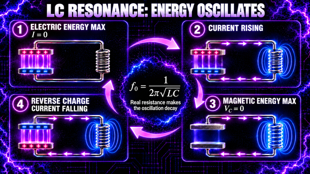
In an ideal LC circuit, energy moves back and forth between:
- the capacitor’s electric field;
- and the inductor’s magnetic field.
The natural resonant frequency is:\[ f_0=\frac{1}{2\pi\sqrt{LC}} \]
At one moment the capacitor is maximally charged and current is zero. A quarter-cycle later the capacitor is discharged, current is at its maximum and energy is in the magnetic field. The process then reverses.
Real circuits contain resistance, radiation and switching losses, so the oscillation decays unless new energy is supplied. A spark-gap discharge can start a damped oscillation or “ringing” waveform whose frequency depends on effective inductance, capacitance and the physical layout.
Stray inductance and capacitance also participate. Long leads, wide loops and component placement can therefore change the output even when the marked parts remain the same.
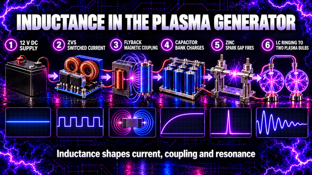
Inductance in the High Frequency Plasma Generator
The generator’s power chain is:
12 V DC supply → ZVS driver → flyback transformer → capacitor banks → adjustable zinc-rod spark gap → two plasma bulbs
Inductance influences several stages.
ZVS driver and flyback primary
The ZVS driver switches current through the flyback primary. Primary inductance and the driver’s resonant components help shape the switching current. The current produces changing magnetic flux in the flyback core.
Flyback transformer
Mutual inductance couples changing flux from primary to secondary. The winding turns, core, frequency, loading and coupling determine the induced waveform. A flyback is not simply a fixed voltage multiplier, and its output must not be assumed to be a clean sine wave.
Capacitor bank and spark gap
The high-voltage output charges the capacitor bank. When the zinc-rod gap breaks down, the bank releases energy into an output network that contains intentional and stray inductance. Capacitance and inductance then exchange energy, producing a fast, damped high-frequency waveform.
Leads, wiring and plasma bulbs
Output wires, connections and the geometry around the bulbs add inductance and capacitance. Changing their length or position can alter resonance, pulse shape, interference and voltage stress.
The system therefore cannot be understood from component values alone. Physical construction is part of the circuit.
How Is Inductance Measured?
An LCR meter measures inductance using a small AC test signal. The result may vary with frequency, current level and whether the core is biased.
An oscilloscope can also estimate inductance from voltage and current waveforms, but high-voltage and high-frequency measurements require correctly rated probes, isolation and careful grounding.
Datasheet inductance is only one specification. Also check:
- test frequency and tolerance;
- maximum current and saturation current;
- winding resistance;
- core-loss limits;
- quality factor \(Q\);
- self-resonant frequency;
- insulation and voltage rating;
- and temperature rise.
Never connect an ordinary handheld LCR meter to an energised or charged high-voltage circuit.
Inductive Safety Hazards
Opening an inductive circuit can generate a voltage far above the original supply voltage. Arcing, insulation breakdown and semiconductor failure can follow.
High-frequency plasma equipment also combines inductive energy with charged capacitors and high-voltage transformer output. Power isolation alone does not prove every part is safe.
Before work begins:
- isolate and secure the supply;
- discharge capacitor banks by their designed method;
- allow magnetic and mechanical systems to settle;
- prove conductors dead with suitable rated equipment;
- use enclosures, interlocks, fuses and correctly rated components;
- and keep the device away from damp conditions and sensitive electronics.
Do not use the equipment if you are pregnant or have a pacemaker or other implanted electronic device. The generator is not medical equipment.
Common Myths About Inductance
Myth 1: An inductor blocks current
It opposes changes in current. After DC becomes steady, an ideal inductor has no induced voltage.
Myth 2: Back emf is extra energy
It is the circuit response associated with changing magnetic flux and the release of stored energy.
Myth 3: More turns always improve a coil
More turns can increase inductance, but also increase resistance, capacitance, size and losses.
Myth 4: Inductance matters only in coils
Every conductor and current loop has inductance. It becomes especially important during fast pulses.
Myth 5: A larger inductor always handles more current
Current capacity depends on wire size, temperature rise, core saturation, construction and cooling—not inductance alone.
Myth 6: Resonance creates energy
Resonance redistributes supplied energy and can build large voltages or currents, but real losses remain and no energy is created.
Frequently Asked Questions
What is inductance in simple words?
Inductance is the tendency of a circuit to generate a voltage when its current changes.
What is the difference between an inductor and inductance?
An inductor is a component, usually a coil. Inductance is the property measured in henries.
Does an inductor store charge?
Not in the way a capacitor does. It stores energy mainly in its magnetic field while current flows.
Why does an inductor make a spark when switched off?
The collapsing magnetic field produces voltage that tries to keep current flowing. If the voltage becomes high enough, it can ionise the gap across the switch.
Does higher frequency increase inductive reactance?
Yes. For a sinusoid, \(X_L=2\pi fL\), so reactance increases with frequency.
Why is a magnetic core used?
It guides magnetic flux and can increase inductance and coupling. It also introduces saturation and core losses.
Is a transformer an inductor?
It contains two or more inductive windings that share magnetic flux. Its operation depends on mutual inductance.
What causes ringing after the spark gap fires?
Energy oscillates between effective capacitance and inductance. Resistance and other losses make the oscillation decay.
Can I change the generator frequency by changing a coil?
Possibly, because inductance affects resonance. But changing a coil also affects current, coupling, saturation and component stress, so the complete system must be evaluated.
What Have We Learned?
Inductance connects changing current, magnetic flux and induced voltage:\[ V_L=-L\frac{dI}{dt} \]
An inductor opposes changes in current and stores energy in its magnetic field:\[ U_L=\frac{1}{2}LI^2 \]
With capacitance, inductance forms a resonant system where energy moves between electric and magnetic fields. In the plasma generator, inductance is essential to ZVS switching, flyback transformer action and the ringing pulse produced after the spark gap conducts.
🧠 Key Takeaways
- Inductance produces voltage when current changes.
- The unit of inductance is the henry.
- An inductor opposes change, not steady current itself.
- Inductive voltage follows \(V_L=-L\,dI/dt\).
- Magnetic-field energy is \(U_L=\tfrac12LI^2\).
- More turns, core permeability and coil geometry affect inductance.
- Mutual inductance is the basis of transformer action.
- Inductive reactance rises with frequency.
- Core saturation can cause current to rise sharply.
- Inductance and capacitance set resonant behaviour.
- Wiring and layout contribute stray inductance.
- Inductive kickback can produce dangerous voltage.
Continue Your Learning Journey
Previous Lesson: Lesson 19 — What Is Capacitance?
Next Lesson: Lesson 21 — How Does a Transformer Work? (Coming Soon)
Further Reading
- OpenStax, University Physics Volume 2: Self-inductance and inductors
- OpenStax, University Physics Volume 2: Energy in a magnetic field and RL circuits
- OpenStax, University Physics Volume 2: Oscillations in an LC circuit
- OpenStax, University Physics Volume 2: Inductive reactance in AC circuits
- UK Health and Safety Executive: Electrical safety precautions
Learn More About High-Frequency Plasma
Explore the complete High Frequency Plasma Learning Centre at HighFrequencyPlasma.com.
Join the Telegram community: https://t.me/HighFrequencyPlasma
Disclaimer
This lesson is for general educational purposes. High-voltage and high-frequency equipment can cause fatal electric shock, severe burns, fire, component rupture, electromagnetic interference and injury from stored energy after power is removed.
Do not construct, open, alter, probe or operate high-voltage equipment unless you are competent and have suitable isolation, enclosures, interlocks, discharge systems and correctly rated test instruments. This generator is not medical equipment and is not intended to diagnose, treat, cure or prevent any condition.
🎉 Lesson Complete
You now understand how inductance links changing current to magnetic flux, how inductors store energy and why inductance works with capacitance throughout a high-frequency plasma generator.
In Lesson 21, we will examine how a transformer works, including primary and secondary windings, turns ratio, magnetic coupling, isolation, losses and waveform behaviour.