
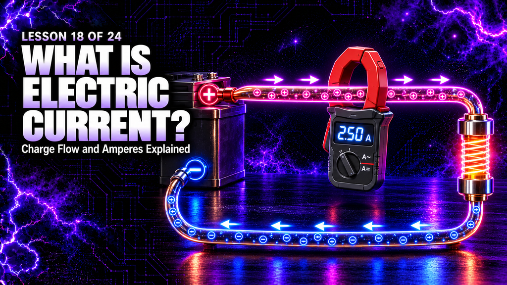
What Is Electric Current? Electric current is the movement of electric charge. It is what carries charge through a wire, moves ions through a plasma, heats a resistor, energises a transformer winding and makes an electrical circuit do useful work.
Lesson 18 of 24 — High Frequency Plasma Learning Centre
The idea sounds simple, but current is often confused with voltage, power or the speed of individual electrons. These are related quantities, yet they are not interchangeable. Voltage is the potential difference that can drive charge; current is the rate at which charge crosses a point; resistance describes how strongly a component opposes that current; and power describes how quickly energy is transferred.
In a high-frequency plasma generator, current also changes character from one stage to the next. The 12 V supply can deliver substantial direct current. The ZVS driver turns that into rapidly alternating or switched current in the flyback primary. The flyback produces a much higher voltage on its secondary, usually with a very different current capability. The capacitor bank stores energy, and the spark gap releases it in short pulses that excite the output circuit and plasma bulbs.
This lesson explains what electric current is, how amperes are defined, why conventional current points opposite to electron drift in a metal, how current behaves in series and parallel paths, what DC, AC and pulsed current mean, how current is measured, and why electrical safety cannot be reduced to a single current number.
What You’ll Learn
By the end of this lesson, you will understand:
- what electric current means in physical terms;
- why current is measured in amperes;
- the equation \(I = \Delta Q / \Delta t\);
- the difference between conventional current and electron flow;
- why charge does not get “used up” as it moves around a circuit;
- why a complete conducting path is normally required for continuous current;
- how voltage, current, resistance and power are related;
- how current behaves in series and parallel circuits;
- the difference between DC, AC and pulsed current;
- what current density and drift velocity mean;
- how an ammeter or current probe measures current;
- why an ammeter must not be placed directly across a voltage source;
- why the current rating of a source is not the same as the current forced through every load;
- and how current changes through a high-frequency plasma generator.
The Short Answer: What Is Electric Current?
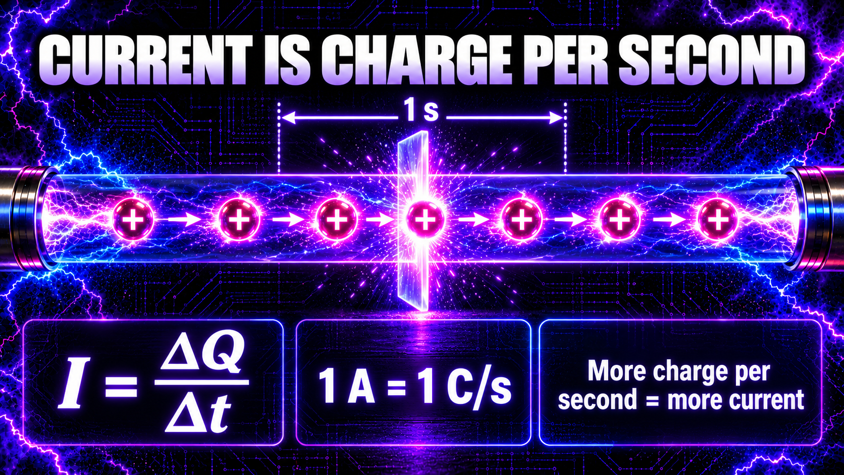
Electric current is the rate at which electric charge passes through a chosen surface or point.
If an amount of charge \(\Delta Q\) passes in a time interval \(\Delta t\), the average current is:\[ I_{\text{average}} = \frac{\Delta Q}{\Delta t} \]
The symbol for current is \(I\). Charge is measured in coulombs (C), time in seconds (s), and current in amperes (A). Therefore:\[ 1\ \text{A} = 1\ \text{C/s} \]
One ampere means that one coulomb of charge passes the chosen cross-section each second. A current of 250 milliamperes is 0.250 A, while 1 microampere is one millionth of an ampere.
For a current that changes from moment to moment, the instantaneous definition is:\[ I = \frac{dQ}{dt} \]
You do not need calculus to use the basic idea. Current answers a practical question: how much net charge is crossing here per second?
What Is an Ampere?
The ampere, often shortened to “amp”, is the SI base unit of electric current. Its symbol is a capital A.
Useful submultiples include:
| Unit | Symbol | Value in amperes |
|---|---|---|
| Ampere | A | \(1\ \text{A}\) |
| Milliampere | mA | \(10^{-3}\ \text{A}\) |
| Microampere | µA | \(10^{-6}\ \text{A}\) |
| Nanoampere | nA | \(10^{-9}\ \text{A}\) |
The modern SI definition fixes the elementary charge at exactly \(1.602176634 \times 10^{-19}\) coulombs. In everyday terms, one coulomb represents the magnitude of charge carried by about \(6.24 \times 10^{18}\) electrons. A steady current of one ampere therefore corresponds to that amount of charge crossing a point each second.
That does not mean a single electron travels from the source to the load in one second. A conductor already contains an enormous population of mobile charge carriers. The electric field acts throughout the circuit, and the carriers acquire a small net drift on top of their rapid, disordered microscopic motion.
Charge Flow Is Not the Same as Energy Flow
One of the most useful distinctions in electricity is the difference between charge and energy.
Charges move through a circuit. A source transfers energy to them, and loads transfer that energy into heat, light, motion, sound, fields or other forms. In a steady circuit, the charge carriers are not normally consumed by the load. The same rate of charge enters a component as leaves it, unless charge is temporarily accumulating somewhere.
Consider a lamp in a simple closed circuit. Electrons enter one terminal and other electrons leave the other terminal. The lamp does not “burn up” electrons. Instead, electrical energy is converted into light and heat while charge continues around the circuit.
This is why the statement “the appliance uses current” can be misleading. An appliance draws current and uses electrical energy. Current is the rate of charge flow associated with that energy transfer.
Conventional Current Versus Electron Flow
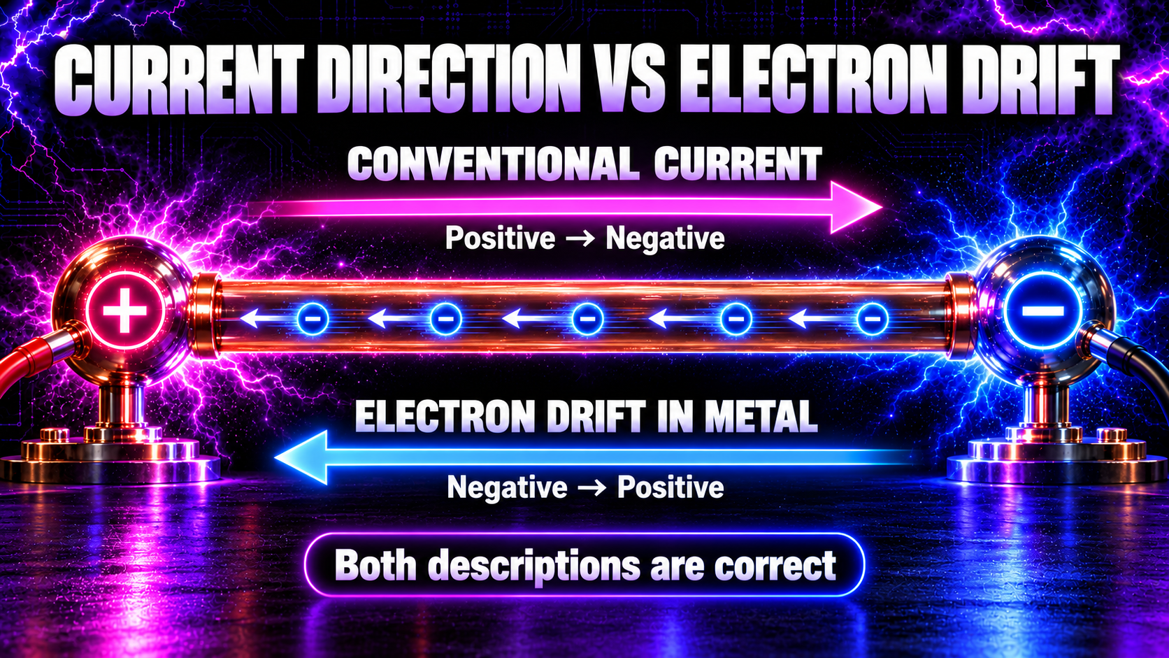
Circuit diagrams use conventional current, defined as the direction in which positive charge would move.
In a simple external DC circuit, conventional current points from the positive terminal of a source, through the load, and towards the negative terminal.
In a copper wire, however, the mobile carriers are negatively charged electrons. Their average drift is in the opposite direction: from the negative side towards the positive side.
Both descriptions are correct because they refer to different things:
- conventional current direction follows the motion a positive charge would have;
- electron drift direction follows the actual average motion of electrons in a metal.
Electrical engineering settled on conventional current before electrons were discovered. Reversing every arrow and rule would create confusion without changing any circuit prediction, so the convention remains.
Current is not always carried only by electrons. Positive and negative ions can carry current in liquids, gases and plasmas. In an ionised gas, electrons and positive ions moving in opposite physical directions can both contribute to conventional current in the same overall direction.
How Can Electrons Drift Slowly While a Lamp Turns On Quickly?
The average drift speed of electrons in a metal can be surprisingly slow. Yet a lamp responds almost immediately when a switch is closed.
The reason is that the electrical effect is not waiting for one electron to travel from the switch to the lamp. The wires already contain mobile electrons throughout their length. Closing the switch establishes an electric field through the circuit, and charges all along the path begin responding.
A useful analogy is a pipe already full of water. If water is pushed into one end, water can emerge from the other end quickly even though an individual water molecule moves only a short distance. The analogy is imperfect, but it captures the difference between the propagation of the driving effect and the slow net motion of individual carriers.
The electromagnetic field and circuit geometry govern how energy is delivered. The electrons provide the mobile charge that responds to the field.
What Causes Electric Current?
Current requires mobile charge carriers and a force that gives them a net motion.
In a metal, a voltage source establishes an electric field inside the conductor. The field exerts force on the mobile electrons. They constantly collide with the atomic lattice and do not accelerate freely without limit; instead, their random motion gains a small average drift.
Different materials provide different charge carriers:
- metals: mainly conduction electrons;
- electrolytes: positive and negative ions;
- semiconductors: electrons and holes;
- ionised gases and plasmas: electrons and positive or negative ions;
- vacuum devices: electrons emitted from a surface and accelerated through vacuum.
A voltage can exist without a sustained current, as across an open switch or a charged capacitor. Current begins only when the conditions allow charge to move. This is why voltage is the cause-like electrical potential difference, while current is the resulting rate of charge transfer—not a substance stored inside a source.
Why Does Current Usually Need a Complete Circuit?
A steady conduction current requires a closed path. In a simple battery-and-lamp circuit, charge must be able to leave one terminal, pass through the lamp and return to the other terminal.
If a switch opens the path, continuous conduction current stops. Voltage may still remain across the open switch, because the two sides can be at different electric potentials.
There are important refinements:
- a capacitor can carry a temporary charging current even though its dielectric blocks steady conduction;
- changing electric fields can couple current through capacitance;
- a spark can bridge a gap after the gas breaks down;
- displacement current is part of the complete electromagnetic description;
- unintended paths can pass through stray capacitance, damp surfaces, shielding, test equipment or a person.
So “the switch is open” does not automatically mean every part of a high-voltage, high-frequency system is safe. Stored charge and parasitic coupling may remain.
Current, Voltage, Resistance and Power
These four quantities describe different aspects of a circuit:
| Quantity | Meaning | Unit |
|---|---|---|
| Voltage \(V\) | Energy difference per unit charge | volt (V) |
| Current \(I\) | Charge passing per unit time | ampere (A) |
| Resistance \(R\) | Opposition to current in an ohmic element | ohm (Ω) |
| Power \(P\) | Energy transferred per unit time | watt (W) |
For an ohmic component under the applicable conditions, Ohm’s law is:\[ V = IR \]
Rearranging gives:\[ I = \frac{V}{R} \]
This equation shows that the current is determined by both the applied voltage and the resistance—not by the voltage alone and not by a source’s maximum current rating alone.
Electrical power is:\[ P = VI \]
For an ohmic resistor, combining the equations gives:\[ P = I^2R = \frac{V^2}{R} \]
Ohm’s law is not a universal rule for every device. Diodes, lamps, arcs, spark gaps, plasmas, transformers and switching circuits can have nonlinear, time-dependent or frequency-dependent behaviour. Their current may need a fuller model than one fixed resistance.
Does a Power Supply “Push” Its Rated Current?
No. A source’s current rating normally states how much current it can supply within specified limits; it does not mean that this current is forced through every connected load.
A 12 V supply rated at 10 A can, in principle, support loads drawing up to its rated current under the manufacturer’s conditions. A load that requires 0.5 A should draw about 0.5 A, not 10 A. The actual current depends on the load, the applied voltage, the wiring and the source’s control or protection behaviour.
If the load demands more than the supply can safely deliver, the supply may limit current, reduce its voltage, shut down, overheat or fail. The exact response depends on its design.
A current-limited supply actively prevents the current from rising above a set value. Once the limit is reached, its output voltage usually falls as necessary. This is a powerful protection feature, but it is not a substitute for correct insulation, fusing, isolation and safe working practice.
Current in a Series Circuit
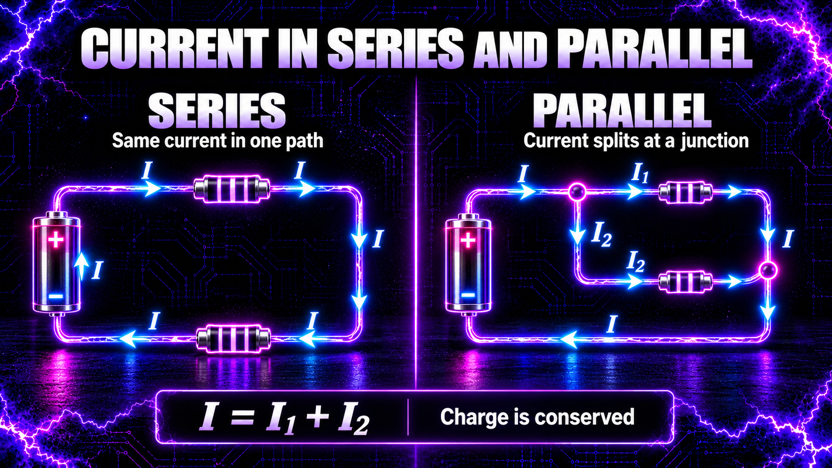
In an ideal series circuit there is only one path, so the same instantaneous current passes through every series component.
If 0.20 A passes through a resistor, lamp and switch connected in one unbranched loop, then 0.20 A passes through each of them. Charge cannot continually disappear between the components. If charge began accumulating at one point, the resulting electric field would change the circuit until the current relationship was restored.
Voltage behaves differently. The source voltage is divided among the series components according to their electrical behaviour. This gives a useful contrast:
- current is common to ideal series elements;
- voltage is distributed across them.
At high frequencies, real wiring also has capacitance and inductance. Parts that look “in series” on a simple drawing may carry local currents influenced by parasitic paths, so physical layout matters.
Current at a Junction and in Parallel Branches
At a circuit junction, current can split into two or more branches. Conservation of charge gives Kirchhoff’s current law:\[ \sum I_{\text{in}} = \sum I_{\text{out}} \]
If 3 A enters a junction and one branch carries 1 A, the remaining branches must together carry 2 A, assuming no net charge is accumulating at the junction.
Parallel branches share the same voltage between their two connection nodes, but they can carry different currents. A lower-resistance branch generally carries more current than a higher-resistance branch at the same voltage, provided the components behave approximately ohmically.
This is another important contrast:
- voltage is common across ideal parallel branches;
- current divides among the branches.
The total current supplied is the sum of the branch currents.
What Is Current Density?
Current tells us the total rate of charge flow through a cross-section. Current density describes how concentrated that flow is within an area.
For a uniform current perpendicular to a conductor’s cross-section:\[ J = \frac{I}{A} \]
where \(J\) is current density in amperes per square metre and \(A\) is cross-sectional area.
The same current through a thinner wire produces a greater current density. Greater current density can mean more heating, a larger voltage drop and greater stress on the conductor. This is one reason wire thickness matters.
Current density is also important in electrodes and plasmas. The total current may be modest, yet if it is concentrated into a tiny arc channel or contact point, local heating can be intense.
What Is Drift Velocity?
In a conductor with charge-carrier number density \(n\), carrier charge magnitude \(q\), cross-sectional area \(A\) and drift-speed magnitude \(v_d\), the current magnitude is:\[ I = nqAv_d \]
This equation explains why a substantial current does not require each electron to race along the wire. Metals contain huge numbers of mobile electrons. A small average drift multiplied by a very large carrier population can produce a large current.
Increasing the cross-sectional area provides more charge carriers across the path. For the same material and drift speed, a larger area permits a larger current. Conversely, forcing the same current through a smaller area raises current density and often increases heating.
What Is Direct Current?
Direct current (DC) has one conventional direction. Its magnitude may be steady or may vary, but it does not reverse direction.
A battery is a familiar DC source. A well-regulated 12 V power supply provides approximately steady DC voltage to a load, and the load draws a corresponding DC current. When a capacitor charges from DC, its current starts higher and then falls as the capacitor voltage approaches the supply voltage.
The phrase “direct current” does not require a perfectly flat waveform. Rectified or pulsating current can still be unidirectional even though its magnitude rises and falls.
What Is Alternating Current?
Alternating current (AC) reverses direction repeatedly. In a sinusoidal AC waveform, the current passes through zero, flows in one conventional direction, returns through zero, and then flows in the opposite direction.
Frequency tells us how many complete cycles occur each second. It is measured in hertz (Hz). A 50 Hz current completes 50 cycles each second.
AC current is commonly described by its root-mean-square value, or RMS. For a pure sine wave:\[ I_{\text{RMS}} = \frac{I_{\text{peak}}}{\sqrt{2}} \]
This relationship applies only to a sinusoid. Distorted, pulsed or resonant waveforms require the actual waveform to be considered when finding RMS, peak and average values.
In reactive circuits, voltage and current may not peak at the same time. Inductors and capacitors can shift the phase between them, and this becomes especially important in high-frequency systems.
What Is Pulsed Current?
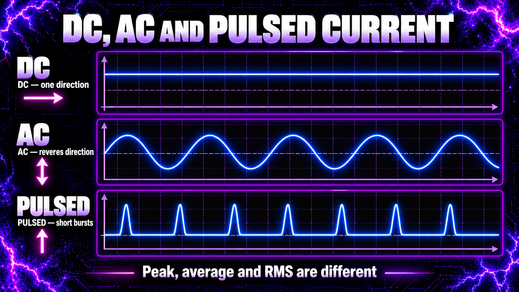
Pulsed current flows in short bursts separated by intervals of lower or zero current. Pulses may be unidirectional or may alternate as part of a ringing waveform.
Important pulse properties include:
- peak current;
- pulse width;
- repetition rate;
- rise and fall time;
- waveform shape;
- duty cycle;
- and energy per pulse.
Two systems can show the same average current while having very different peak currents. A low duty-cycle waveform may contain narrow, high-current pulses but a much smaller average over a complete cycle.
Spark-gap circuits are strongly pulsed. Charge builds on a capacitor until the gap breaks down, after which stored energy is released rapidly into the connected circuit. The resulting current can oscillate or “ring” because capacitance and inductance exchange energy.
Average, RMS and Peak Current
One current number cannot always describe a changing waveform.
- Peak current is the largest instantaneous magnitude.
- Average current is the time average, with positive and negative directions carrying signs.
- Average absolute current ignores direction and averages magnitude.
- RMS current relates to the heating effect in a resistor.
For a symmetrical sine wave, the ordinary signed average over a complete cycle is zero even though the waveform can heat a resistor and transfer power. Its RMS value is not zero.
Meters differ in what they report. A true-RMS instrument designed for the relevant bandwidth may estimate RMS accurately for certain nonsinusoidal signals. A basic meter may assume a sine wave, miss fast pulses or exceed its input limits. Instrument specifications and probe bandwidth matter.
How Does Current Create a Magnetic Field?
Moving charge creates a magnetic field. Around a straight wire carrying current, the magnetic field forms closed loops around the conductor. Reversing the current reverses the field direction.
Coiling the conductor concentrates and organises this magnetic field. That is the foundation of electromagnets, inductors and transformer windings.
When current in the flyback primary changes rapidly, its magnetic field also changes rapidly. The changing magnetic flux induces voltage in the secondary winding. The flyback therefore depends not merely on current existing, but on current changing with time.
This connects directly to Lesson 15 on magnetic fields and Lesson 16 on electromagnetic induction.
Current Through Capacitors and Inductors
Capacitors and inductors respond differently to changing current and voltage.
For an ideal capacitor:\[ I = C\frac{dV}{dt} \]
A rapid voltage change produces a larger current for a given capacitance. Steady DC current falls to zero after an ideal capacitor is fully charged, but alternating or pulsed voltage can produce repeated charging and discharging current.
For an ideal inductor:\[ V = L\frac{dI}{dt} \]
An inductor opposes sudden changes in current. A faster attempted current change produces a larger induced voltage for a given inductance.
These relationships explain why high-frequency circuits cannot be analysed using resistance alone. Capacitance, inductance, frequency, switching speed and resonance all influence the current.
What Limits Current in a Real Circuit?
Several effects can limit current:
- resistance in wires and components;
- source impedance;
- inductive reactance;
- capacitive reactance;
- semiconductor switching limits;
- magnetic-core saturation;
- current-limiting control circuits;
- fuses or circuit breakers;
- plasma and arc impedance;
- contact resistance;
- and energy available in charged capacitors.
At high frequency, reactance can dominate. The capacitive reactance magnitude is:\[ X_C = \frac{1}{2\pi fC} \]
and the inductive reactance is:\[ X_L = 2\pi fL \]
As frequency rises, an ideal capacitor offers less reactance while an ideal inductor offers more. Real components also have losses, parasitic capacitance, parasitic inductance and frequency limits.
How Is Electric Current Measured?
Current must be measured with the correct method, rating and bandwidth.
Ammeter or multimeter in current mode
An ammeter is inserted in series with the circuit so the current passes through the meter. The meter has a low internal resistance and measures the voltage across an internal shunt or uses another sensing method.
Placing a meter set to current mode directly across a voltage source can create a near short circuit. That can blow the meter fuse, damage the instrument, produce an arc or cause injury. The meter’s input terminals, current range, fuse type and category rating must all be correct.
Current clamp
A clamp meter senses the magnetic field around a conductor. Some clamps measure AC only; others can measure AC and DC. The clamp normally encloses one conductor, not both outgoing and return conductors together, because equal opposing currents can cancel their magnetic fields.
Current transformer
A current transformer measures alternating current and provides isolation when correctly designed and used. Its secondary must be treated according to the manufacturer’s requirements; opening the secondary of an energised current transformer can create hazardous voltage.
Shunt resistor and oscilloscope
A known low resistance can convert current into a measurable voltage:\[ V_{\text{shunt}} = IR_{\text{shunt}} \]
This method can reveal fast waveforms, but it can also disturb the circuit and create grounding hazards. High-side, floating and high-frequency measurements require suitable differential or isolated equipment and expert technique.
Current probe
Oscilloscope current probes use magnetic sensing to display a current waveform without opening the conductor. Their bandwidth, maximum current, insulation and transient ratings must suit the circuit.
Why High-Frequency Current Is Difficult to Measure
High-frequency plasma circuits combine fast edges, high voltage, pulsed current, electromagnetic interference and stray coupling. A measurement lead can add enough inductance or capacitance to change the circuit being measured.
Common problems include:
- probe bandwidth too low to capture the waveform;
- saturation of a current transformer or magnetic probe;
- excessive common-mode voltage;
- long ground leads creating loops and false ringing;
- a shunt resistor adding unwanted inductance;
- an oscilloscope ground connecting a live node to protective earth;
- measuring only average current while missing damaging peaks;
- and instrument ratings being exceeded by transients.
The safe solution is not to improvise. Use equipment rated for the expected voltage, current, frequency, energy and measurement category, and follow the instrument manufacturer’s connection method. When the waveform or circuit reference is uncertain, measurement should be planned by someone competent in high-voltage, high-frequency work.
Does Current Determine Electrical Danger?
Current through the body can cause injury, but there is no single source-current number that fully predicts risk. The actual outcome depends on the current path, duration, waveform, frequency, contact area, skin condition, source impedance, available energy and surrounding conditions.
Voltage matters because it helps drive current through an impedance. Stored energy matters because capacitors can deliver intense pulses. Frequency matters because biological and heating effects vary with waveform. A source described as “current limited” can still be dangerous if its limit, voltage or stored energy is inappropriate.
An RCD can reduce the likelihood of some electric-shock injuries by disconnecting a supply when it detects certain leakage-current imbalances, but it does not detect every fault and must be treated as secondary protection. It does not make exposed conductors safe to touch.
For this learning project:
- never work on an energised circuit;
- isolate the supply before opening or adjusting equipment;
- verify that stored capacitors are discharged using a correctly designed method;
- use barriers, interlocks, fuses, enclosures and properly rated components;
- keep the equipment away from water, damp conditions and flammable materials;
- do not use it near sensitive electronics;
- do not use it if you are pregnant or have a pacemaker or other implanted electronic device;
- and do not treat the device as medical equipment.

How Current Changes Through the High Frequency Plasma Generator
There is not one identical current value everywhere in the generator. Transformer action, branching, switching, capacitance, resonance and spark-gap conduction all shape the current at each stage.
Stage 1: Mains input to the power supply
The power supply draws AC current from the local mains. Its input current depends on output load, efficiency, power factor and internal design. Mains values differ by country, so no universal input-current number should be assumed.
Stage 2: 12 V DC output
The supply provides low-voltage DC to the ZVS driver. Because power is roughly voltage multiplied by current, the 12 V side may carry substantial current even when the high-voltage side carries much less average current. Conversion losses mean input and output power are never exactly equal.
Stage 3: ZVS driver and flyback primary
The ZVS driver switches current through the flyback primary winding. The primary current is time-varying and produces a changing magnetic field in the core. Its waveform depends on the driver topology, load, resonant components, supply and transformer.
Stage 4: Flyback secondary
The changing magnetic flux induces high voltage in the secondary. The secondary current capability is generally much lower than the low-voltage primary-side current, but the exact waveform and magnitude depend on the flyback’s winding, rectification, load and operating frequency. Never assume it is a clean sine wave or assign it an unverified current value.
Stage 5: Capacitor banks
Current charges the capacitor banks between spark events. When the spark gap conducts, the capacitors can discharge rapidly. This produces short currents whose peaks may be far greater than the long-term average charging current.
Stage 6: Adjustable zinc-rod spark gap
Before breakdown, the gap carries almost no conduction current, although stray capacitive current can exist. Once the electric field ionises the gas sufficiently, the gap becomes conductive and releases a pulse into the output circuit. The current then falls as stored energy is transferred and the arc extinguishes.
Stage 7: Two plasma bulbs
The pulsed, high-frequency output drives charge motion in the ionised gas and around the glass bulbs through the complete electromagnetic system. Electrons and ions contribute to the plasma current. The current distribution is not necessarily equal in both bulbs unless the output network and loads are symmetrical.
This chain is best understood as repeated energy conversion: mains power becomes regulated low-voltage DC, then switched magnetic energy, high-voltage electrical energy, stored capacitor energy and finally pulsed high-frequency excitation of the plasma load.
Common Myths About Electric Current
Myth 1: Current is stored in a battery
A battery stores chemical energy and separated charge conditions. Current is the rate of charge flow that occurs when a circuit is connected.
Myth 2: Electrons are used up by a lamp
Charge circulates; energy is transferred. In steady operation, the same current enters and leaves the lamp.
Myth 3: Conventional current follows electron motion
In metal wires they point in opposite directions. Conventional current follows the direction positive charge would move.
Myth 4: A 10 A supply always pushes 10 A
The rating is a capability or limit. The connected circuit determines the current, within the source’s operating range.
Myth 5: Current is the same everywhere in every circuit
It is the same through ideal series elements, but it divides at branches and can differ greatly across transformer stages and converter sections.
Myth 6: An open switch guarantees zero electrical activity
Voltage, stored charge, leakage, stray capacitance and high-frequency coupling can remain.
Myth 7: AC has no net current, so it transfers no power
A symmetrical AC current has zero signed average over a full cycle, yet its RMS value and heating effect are nonzero.
Myth 8: Low average current means low peak current
Pulsed circuits can have large peaks and a small average. Both values and the waveform matter.
Myth 9: High-frequency current is automatically harmless
Frequency changes how current behaves, but it does not remove shock, burn, arc, stored-energy or interference hazards.
Myth 10: Any multimeter can measure any current
Meters have strict current, voltage, fuse, category and bandwidth limits. The wrong connection or range can be dangerous.
Frequently Asked Questions
What is electric current in simple words?
Electric current is the rate at which electric charge passes a point. One ampere equals one coulomb of charge per second.
Why is current represented by the letter I?
The symbol is historically associated with the French phrase intensité du courant, meaning current intensity.
What is the difference between voltage and current?
Voltage is energy difference per unit charge between two points. Current is charge flow per unit time through a surface or path.
Does current flow from positive to negative?
Conventional current does. In a metal, electrons drift in the opposite direction, from negative towards positive.
Can current flow without voltage?
Ordinary resistive current requires an electric field associated with a potential difference. Some special cases, such as persistent current in a superconducting loop, need more careful description, but they do not change the basic rule for normal circuits.
Can voltage exist without current?
Yes. There can be voltage across an open switch, disconnected terminals or a charged capacitor even when no continuous conduction current flows.
Is one ampere a lot?
It depends on the circuit, voltage, path, duration and application. One ampere is normal in many appliances but can be destructive or extremely dangerous in the wrong place. Never judge safety from current alone.
How many electrons make one ampere?
One ampere corresponds to about \(6.24 \times 10^{18}\) elementary charges crossing a point each second.
Does current get weaker after a resistor?
In a single ideal series loop, the same current flows before and after the resistor. The resistor has a voltage drop and converts electrical energy, but charge does not disappear inside it.
Why does a thinner wire get hotter?
For the same current, a thinner wire has greater current density and usually greater resistance per unit length. Its resistive heating can therefore be greater.
What happens to current at a junction?
It divides among the available branches. The sum of currents entering the junction equals the sum leaving, provided charge is not accumulating there.
Is AC current faster than DC current?
“Faster” is not the right comparison. AC reverses direction at a specified frequency; DC remains in one direction. Either can change rapidly or slowly depending on its waveform.
What current reaches the plasma bulbs?
It cannot be inferred safely from the 12 V supply rating. The flyback, capacitor banks, spark gap, output network, frequency and plasma load all shape the pulsed current. It must be measured with suitable high-voltage, high-frequency equipment and technique.
Why can a capacitor deliver a large current pulse?
A charged capacitor stores energy in an electric field. If connected through a low-impedance path, it can release that energy quickly, producing a high peak current even when its earlier charging current was modest.
Can I measure current by touching probes across a component?
Not with a meter set to current mode. An ammeter is normally connected in series. Putting it across a source or component may create a short circuit. Follow the meter manufacturer’s instructions and use a competent person for hazardous circuits.
What Have We Learned?
Electric current is not “electricity” as a vague substance. It is a precise rate: charge per unit time.
The central equation is:\[ I = \frac{\Delta Q}{\Delta t} \]
and one ampere equals one coulomb per second.
Conventional current follows the direction positive charge would move. In metal wires, electrons drift the other way. Charges are not normally consumed by a load; instead, the circuit transfers energy from the source to the load.
Current is the same through ideal elements in one unbranched series path, while it divides among parallel branches. DC stays in one direction, AC reverses direction, and pulsed current arrives in bursts. For changing waveforms, peak, average and RMS current answer different questions.
In the high-frequency plasma generator, the current on the 12 V side is not the same as the current in the flyback secondary or the spark-gap output. Each conversion stage changes the voltage, current, waveform and impedance. Measurement therefore requires suitable instruments, correct connections and serious respect for high voltage, stored energy and high-frequency transients.
🧠 Key Takeaways
- Electric current is the rate of charge flow.
- \(I = \Delta Q / \Delta t\).
- One ampere equals one coulomb per second.
- Conventional current points in the direction positive charge would move.
- Electron drift in a metal is opposite to conventional current.
- Charge carriers move; energy is transferred.
- A steady current normally needs a complete conducting path.
- Current is common in a series path and divides at junctions.
- A source’s amp rating is a capability, not a fixed current forced into every load.
- DC, AC and pulsed current have different waveform behaviour.
- Average, RMS and peak current are not interchangeable.
- Current creates magnetic fields, and changing current enables induction.
- High-frequency current is shaped by resistance, inductance, capacitance and parasitic effects.
- Measuring current incorrectly can short the circuit and create severe danger.
- High voltage, stored energy and pulsed current must never be treated as harmless.
🔬 Current Fact
A steady current of just one ampere represents roughly 6.24 quintillion elementary charges per second crossing a point. Yet the average drift of any one electron in a metal can be slow—the circuit responds quickly because the conductor already contains charge carriers throughout its length and the electromagnetic field propagates through the circuit.
Continue Your Learning Journey
Previous Lesson: Lesson 17 — What Is Voltage?
Next Lesson: Lesson 19 — What Is Capacitance? (Coming Soon)
Further Reading
- OpenStax, College Physics 2e: Current
- OpenStax, University Physics Volume 2: Current, resistance, Ohm’s law and electrical power
- NIST: The ampere and the modern SI definition
- UK Health and Safety Executive: Electrical safety at work and safe use of electrical equipment
Learn More About High-Frequency Plasma
Explore the complete High Frequency Plasma Learning Centre at HighFrequencyPlasma.com.
For project updates and discussion, join the Telegram channel: https://t.me/HighFrequencyPlasma
Disclaimer
This lesson is for general educational purposes. High-voltage and high-frequency equipment can cause electric shock, deep or surface burns, fire, component rupture, electromagnetic interference and injury from stored energy even after power is removed.
Do not construct, open, adjust, probe or operate high-voltage equipment unless you are competent to do so and have appropriate isolation, enclosures, interlocks, discharge systems, protective equipment and correctly rated test instruments. Never rely on an apparent lack of output, an open switch or a current-limited supply as proof that a circuit is safe.
This plasma generator is not medical equipment and is not intended to diagnose, treat, cure or prevent any condition. Do not use it if you are pregnant or have a pacemaker or other implanted electronic device. Keep it away from sensitive electronics and follow all applicable electrical-safety requirements.
🎉 Lesson Complete
You now understand what electric current is, how amperes measure charge flow, why current direction differs from electron drift, how current divides in circuits and how it changes through the high-frequency plasma generator.
In Lesson 19, we will study capacitance: how separated conductors store charge and energy, why capacitor size and spacing matter, how capacitors charge and discharge, and why capacitor banks are central to spark-gap plasma systems.