
What Is Capacitance? Capacitance is the ability of a system to store separated electric charge—and therefore electrical energy—when a voltage exists between two conductors. The component designed to provide capacitance is called a capacitor.
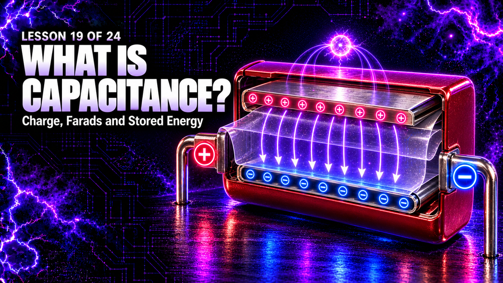
Capacitors appear in almost every kind of electronic equipment. They smooth power supplies, store short bursts of energy, block steady DC while coupling changing signals, set timing intervals, tune resonant circuits and suppress unwanted electrical noise. In a high-frequency plasma generator, the capacitor banks perform an especially important job: they accumulate energy from the high-voltage source and release it rapidly when the spark gap conducts.
Capacitance is often described using the equation \(C = Q/V\), but the subject becomes much clearer when we understand what the symbols represent. A capacitor does not create charge, multiply power or hold voltage forever. It separates equal quantities of positive and negative charge, stores energy in its electric field, and responds to changes in voltage according to the complete circuit around it.
This lesson explains what capacitance is, how capacitors work, what a farad means, how plate area, spacing and dielectric material affect capacitance, how capacitors behave in series and parallel, how they charge and discharge, and why voltage rating, pulse current and stored energy are critical in a spark-gap plasma system.
Lesson 19 of 24 — High Frequency Plasma Learning Centre
What You’ll Learn
By the end of this lesson, you will understand:
- what capacitance means in physical terms;
- the relationship \(C = Q/V\);
- why capacitance is measured in farads;
- how a capacitor stores separated charge and electric-field energy;
- how plate area, separation and dielectric material affect capacitance;
- the difference between capacitance, charge, voltage and energy;
- how capacitors behave with steady DC, AC and pulses;
- how to calculate capacitors in series and parallel;
- why series voltage sharing is not automatically equal in a real bank;
- how an RC circuit charges and discharges;
- what ESR, ESL, leakage and self-resonance mean;
- why pulse-rated film capacitors are used in demanding high-frequency circuits;
- how the capacitor banks work with the flyback and spark gap;
- and why a disconnected capacitor can remain dangerous.

The Short Answer: What Is Capacitance?
Capacitance is the amount of charge a system can store per volt of potential difference.
It is defined by:\[ C = \frac{Q}{V} \]
where:
- \(C\) is capacitance in farads;
- \(Q\) is the magnitude of charge on either conductor in coulombs;
- \(V\) is the voltage between the conductors in volts.
Rearranging gives:\[ Q = CV \]
A capacitor with greater capacitance stores more charge at the same voltage. A capacitor at a higher voltage stores more charge if its capacitance stays constant.
Capacitance does not tell us the present voltage by itself. A 1 µF capacitor may be uncharged at 0 V, partially charged, or charged close to its rated limit. Its capacitance describes the relationship between charge and voltage, not its current state of charge.
What Is a Capacitor?
A capacitor contains two conductive regions separated by an insulating material or gap. The conductors are commonly called plates, even when they are made from rolled metal film, deposited layers, foil or another shape.
The insulating region is the dielectric. It may be air, vacuum, ceramic, plastic film, glass, mica, paper, an oxide layer or another insulating material.
When a voltage source is connected:
- electrons are moved onto one conductor;
- electrons are removed from the other conductor;
- the two conductors acquire equal and opposite net charges;
- an electric field develops through the dielectric;
- energy is stored in that electric field.
Charge does not normally cross through an ideal dielectric. During charging, current flows in the external wires while charge builds on the plate surfaces. When the capacitor voltage matches the applied steady DC voltage, the ideal charging current falls to zero.
Real capacitors are not perfect. They have small leakage current, internal resistance, internal inductance and limits on voltage, temperature, frequency and pulse current.
What Is a Farad?
The farad is the SI unit of capacitance. Its symbol is F.
From \(C = Q/V\):\[ 1\ \text{F} = 1\ \text{C/V} \]
One farad means that one coulomb of separated charge produces one volt across the capacitor. A farad is very large for many electronic circuits, so smaller units are common:
| Unit | Symbol | Value in farads |
|---|---|---|
| Farad | F | \(1\ \text{F}\) |
| Millifarad | mF | \(10^{-3}\ \text{F}\) |
| Microfarad | µF | \(10^{-6}\ \text{F}\) |
| Nanofarad | nF | \(10^{-9}\ \text{F}\) |
| Picofarad | pF | \(10^{-12}\ \text{F}\) |
Unit conversion matters. For example:\[ 4.7\ \text{nF} = 4{,}700\ \text{pF} = 0.0047\ \mu\text{F} \]
Confusing nanofarads and microfarads introduces a factor of one thousand, so the unit prefix must always be checked.
Capacitance, Charge, Voltage and Energy Are Different
These four ideas are closely connected but not interchangeable:
| Quantity | Meaning | Unit |
|---|---|---|
| Capacitance \(C\) | Charge stored per volt | farad (F) |
| Charge \(Q\) | Amount of separated electric charge | coulomb (C) |
| Voltage \(V\) | Potential difference between conductors | volt (V) |
| Energy \(U\) | Work stored in the electric field | joule (J) |
For an ideal linear capacitor, capacitance is mainly set by geometry and dielectric material. Connecting it to a different voltage changes \(Q\) and the stored energy, but it does not normally change the stated capacitance substantially.
This is similar to the capacity of a container. The container size is not the same as the amount currently inside it. The analogy has limits, but it helps separate capacitance from charge.

Where Is the Energy Stored?
A charged capacitor stores energy in the electric field between and around its conductors. The energy is:\[ U = \frac{1}{2}CV^2 \]
Equivalent forms are:\[ U = \frac{Q^2}{2C} \]
and:\[ U = \frac{1}{2}QV \]
The first form reveals an important safety fact: stored energy rises with the square of voltage.
If the voltage across the same capacitor doubles, the stored energy becomes four times greater. If voltage triples, energy becomes nine times greater. This is why even a capacitance that looks numerically small can store significant and dangerous energy at high voltage.
The energy is not “inside the charge” in a simple mechanical sense. It belongs to the complete electric-field configuration created by separating charge on the conductors.
How Does a Parallel-Plate Capacitor Work?
The simplest model uses two flat conductive plates, each with area \(A\), separated by distance \(d\). With vacuum between them:\[ C = \varepsilon_0\frac{A}{d} \]
With a dielectric of relative permittivity \(\varepsilon_r\):\[ C = \varepsilon_0\varepsilon_r\frac{A}{d} \]
This shows three major design relationships:
- larger plate area increases capacitance;
- smaller plate separation increases capacitance;
- a dielectric with greater relative permittivity increases capacitance.
The equation is an idealised parallel-plate model. Real capacitors use rolled, stacked, interleaved or deposited structures to fit a large effective plate area into a compact package. Edge fields, electrode thickness and construction details also matter.
What Does a Dielectric Do?
A dielectric is an electrical insulator that becomes polarised in an electric field. Its bound positive and negative charges shift slightly in opposite directions. This polarisation changes the field inside the capacitor and allows more free charge to be stored at a given voltage than the same geometry would store with vacuum alone.
The dielectric performs several functions:
- separates the conductors;
- helps prevent direct conduction;
- increases capacitance;
- influences the maximum safe voltage;
- affects losses and heating;
- affects stability with temperature and frequency;
- and influences how well the capacitor survives fast pulses.
Every dielectric has limits. If the electric field becomes too strong, the material can break down. Breakdown may puncture the dielectric, create an arc, carbonise material, short the capacitor or cause a violent failure.
A voltage rating is therefore not a target. It is a maximum operating boundary defined under specified conditions. Repetitive pulses, temperature, waveform, frequency and expected lifetime may require substantial design margin.
Does a Capacitor Store Positive and Negative Charge?
Yes—but the capacitor as a whole normally remains close to electrically neutral.
If one plate carries \(+Q\), the other carries \(-Q\). The magnitude \(Q\) in the capacitance equation means the magnitude of charge on either plate, not the sum of the two magnitudes.
The source moves electrons from one plate to the other through the external circuit. It does not create net charge from nothing. One conductor develops an electron surplus and the other an equal deficit.
In a real circuit, nearby conductors, earth, shielding and stray capacitance can affect charge distribution. The two-plate model remains the essential starting point.
How Does a Capacitor Charge?
Suppose an uncharged capacitor is connected to a DC supply through a resistor.
At the instant the switch closes, the capacitor voltage is initially zero. The voltage difference across the resistor is therefore greatest, so the charging current is at its maximum:\[ I_0 = \frac{V_{\text{supply}}}{R} \]
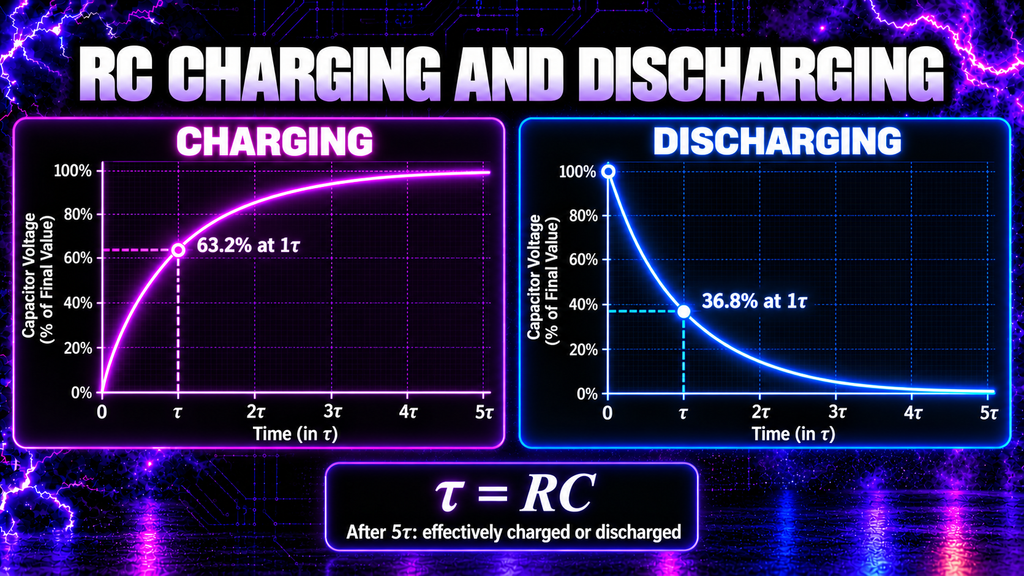
As charge accumulates, the capacitor voltage rises. The voltage left across the resistor falls, so the current decreases. For an ideal RC circuit:\[ V_C(t) = V_{\text{supply}}\left(1-e^{-t/RC}\right) \]
The product \(RC\) is the time constant:\[ \tau = RC \]
After one time constant, the capacitor voltage has reached about 63.2% of its final value. After five time constants it is above 99% of the final value and is commonly treated as effectively charged for practical calculations.
How Does a Capacitor Discharge?
When a charged capacitor is connected across a resistor, its stored energy drives current through the circuit. The voltage falls exponentially:\[ V_C(t) = V_0e^{-t/RC} \]
After one time constant, the voltage has fallen to about 36.8% of its starting value. After five time constants it has fallen below 1%.
This simple calculation assumes a known resistor and an ideal capacitor. High-voltage systems may contain multiple discharge paths, dielectric absorption, leakage, switching devices and isolated nodes. A capacitor can also regain some terminal voltage after an initial discharge because charge trapped within the dielectric redistributes—a phenomenon called dielectric absorption.
For that reason, safe discharge is a designed procedure, not a quick spark from a screwdriver. Proper systems use rated discharge resistors, guarded connections, verification with suitable test equipment and enough time for every stored-energy section to become safe.
What Is the Capacitor Current Equation?
For an ideal capacitor:\[ I = C\frac{dV}{dt} \]
Current depends on how quickly the voltage changes. A steady voltage produces no continuous ideal capacitor current after charging. A rapidly changing voltage can produce a large current even when the capacitance is small.
This is why capacitors strongly influence pulse and high-frequency circuits. A fast voltage rise gives a large \(dV/dt\), and the connected circuit must handle the resulting current.
The equation also explains why a capacitor seems to “pass AC” while blocking steady DC. It does not require charge to travel through the dielectric. Instead, charge moves onto and off the plates as the voltage changes, producing current in the external circuit.
How Does Capacitance Behave With Frequency?
For a pure sinusoidal signal, the magnitude of capacitive reactance is:\[ X_C = \frac{1}{2\pi fC} \]
where \(f\) is frequency.
As frequency increases, ideal capacitive reactance decreases. The capacitor therefore offers less opposition to higher-frequency sinusoidal current than to lower-frequency current, assuming the same capacitance.
Voltage and current are also phase-shifted. In an ideal capacitor driven by a sine wave, current leads voltage by 90 degrees.
Real capacitors stop behaving ideally at sufficiently high frequency. Lead inductance, internal connections and construction create equivalent series inductance. At the self-resonant frequency, capacitive and inductive effects balance. Above it, the component may behave increasingly like an inductor.
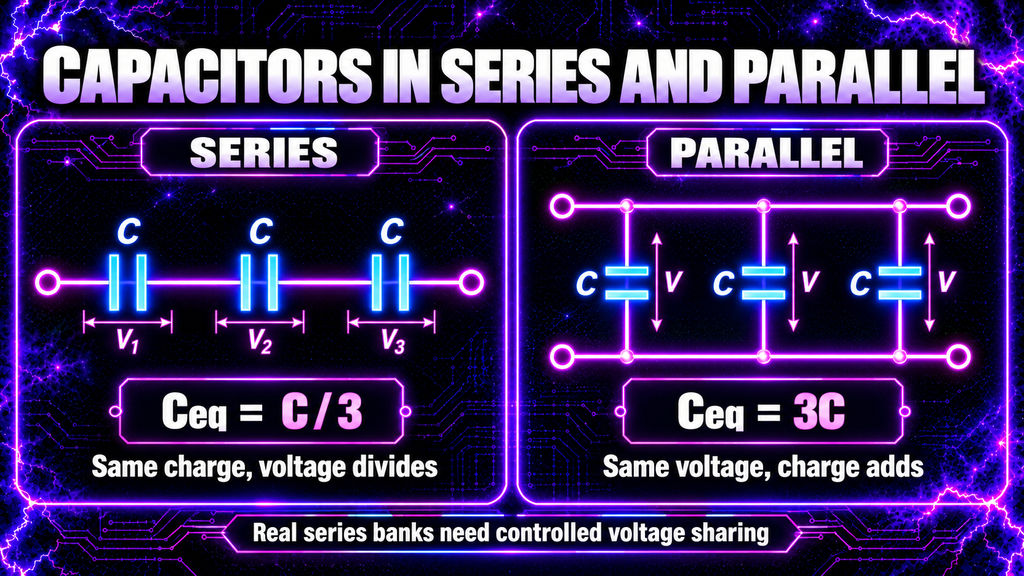
Capacitors in Parallel
Parallel capacitors are connected across the same two nodes, so each has the same voltage.
Their equivalent capacitance is:\[ C_{\text{parallel}} = C_1 + C_2 + C_3 + \cdots \]
Three identical capacitors of capacitance \(C\) in parallel give:\[ C_{\text{equivalent}} = 3C \]
Parallel connection increases total capacitance and therefore increases the charge and energy stored at a given voltage. It can also share current among components, although real sharing depends on resistance, inductance, layout, tolerances and temperature.
The voltage rating of the parallel bank does not become the sum of the individual voltage ratings. Each capacitor experiences the full bank voltage.
Capacitors in Series
For capacitors in series:\[ \frac{1}{C_{\text{series}}} = \frac{1}{C_1}+\frac{1}{C_2}+\frac{1}{C_3}+\cdots \]
Three identical capacitors of capacitance \(C\) in series give:\[ C_{\text{equivalent}} = \frac{C}{3} \]
The ideal series capacitors carry the same charge magnitude, while the total voltage divides between them. For identical ideal capacitors, the voltage divides equally.
Real voltage sharing may be unequal because capacitance tolerance, leakage current, insulation resistance, temperature and transient behaviour differ. Designers may use balancing resistors or other grading networks and must consider their power rating, insulation and effect on discharge time.
It is unsafe to assume that three capacitors rated at 4 kV automatically create a reliable 12 kV bank under every pulsed condition. The whole design must account for voltage sharing, peak and repetitive voltage, polarity, pulse current, dielectric stress, creepage, clearance and manufacturing tolerances.
Series Versus Parallel at a Glance
| Property | Capacitors in series | Capacitors in parallel |
|---|---|---|
| Equivalent capacitance | Less than the smallest individual value | Sum of all capacitances |
| Charge in ideal network | Same magnitude on each | Divides according to capacitance |
| Voltage | Divides across components | Same across every component |
| Common purpose | Voltage distribution, lower effective capacitance | Greater capacitance and stored charge |
| Important caution | Real voltage sharing may be unequal | Each unit sees the full bank voltage |
Mixed series-parallel networks combine these effects. The correct equivalent capacitance must be calculated from the actual electrical connections—not from the number of components or their physical arrangement on a board.
What Are ESR and ESL?
An actual capacitor can be modelled as an ideal capacitance plus unwanted properties.
Equivalent series resistance (ESR)
ESR represents internal losses in electrodes, connections and dielectric material. Current through ESR produces heating:\[ P_{\text{loss}} \approx I_{\text{RMS}}^2R_{\text{ESR}} \]
High ripple or pulse current can therefore overheat a capacitor even when its voltage stays below the marked rating.
Equivalent series inductance (ESL)
ESL comes from leads, electrodes and current-loop geometry. Rapid current changes create voltage across this inductance:\[ V = L\frac{dI}{dt} \]
Long leads and large loop area increase unwanted inductance. In a fast pulse circuit, layout can be as important as the nominal capacitance.
Leakage resistance
The dielectric is not a perfect insulator. A small leakage current flows and slowly discharges the capacitor. Leakage varies with type, voltage, temperature and age.
These parasitic properties determine how a capacitor behaves beyond the simplified schematic symbol.
What Is Self-Resonance?
The capacitor’s capacitance and its unwanted series inductance form a resonant circuit. At the self-resonant frequency, their reactances cancel.
Below self-resonance, the component is mainly capacitive. Near resonance, its impedance may reach a minimum set largely by losses. Above resonance, inductive behaviour can dominate.
This is one reason a physically smaller capacitor with shorter connections may perform better at high frequency than a much larger component with the same nominal capacitance. Datasheets may provide impedance curves, resonant frequency, pulse capability and \(dV/dt\) limits.
Common Capacitor Types
Ceramic capacitors
Ceramic capacitors cover values from tiny RF capacitors to larger multilayer devices. Some types are very stable, while high-capacitance ceramics can change value substantially with applied DC voltage, temperature and ageing.
Film capacitors
Film capacitors use plastic dielectric films such as polypropylene or polyester. Polypropylene film types are widely used where low loss, pulse handling and stability matter. Construction and datasheet ratings still determine suitability.
Electrolytic capacitors
Electrolytic capacitors provide relatively large capacitance in a compact size. Most are polarised and can fail if connected backwards or exposed to excessive ripple current or voltage. They are not interchangeable with high-voltage pulse film capacitors.
Mica and specialised high-voltage capacitors
Mica, ceramic doorknob and other specialised capacitors can be designed for high voltage, RF current or pulse service. Their capacitance, voltage, dissipation factor, current and frequency ratings must match the application.
No capacitor type is universally best. The correct choice depends on the entire waveform and operating environment.
Understanding Capacitor Ratings
A safe design checks more than the printed capacitance and voltage.
Important specifications include:
- nominal capacitance and tolerance;
- DC and AC voltage ratings;
- peak and repetitive pulse voltage;
- permitted \(dV/dt\);
- peak and RMS current;
- dissipation factor or loss tangent;
- ESR and ESL;
- self-resonant frequency;
- operating temperature;
- insulation resistance and leakage;
- dielectric strength;
- pulse life and expected lifetime;
- lead spacing and mechanical construction;
- creepage and clearance requirements;
- and failure mode.
A 4 kV DC marking does not automatically mean the capacitor is suitable for every 4 kV AC, resonant or repetitive pulse waveform. Datasheet conditions and derating must be followed.
What Is Stray Capacitance?
Any two conductors separated by insulation have some capacitance, whether or not a capacitor component was intentionally fitted.
Stray capacitance exists between:
- adjacent wires;
- transformer windings;
- circuit-board tracks;
- a circuit and its enclosure;
- a device and earth;
- a person and nearby equipment;
- and the electrodes of an open spark gap.
At low frequency these capacitances may have little effect. At high frequency, their reactance falls and they can carry significant displacement current, alter resonance, couple interference or create unexpected voltage paths.
This is why high-frequency systems depend strongly on physical layout, cable position, enclosure geometry and test-probe placement.
What Is Dielectric Absorption?
After a capacitor is charged and then discharged, some dielectric materials can release previously polarised charge slowly. The terminal voltage may partially recover even after it initially measured close to zero.
This phenomenon is called dielectric absorption or voltage soakage. It is important in precision circuits and is also a safety concern in high-voltage equipment.
A capacitor that has been discharged must remain connected to an appropriate discharge network as required by the design, and its voltage must be verified before contact. Shorting it briefly and assuming it will remain at zero is unsafe.
How Are Capacitors Measured?
Capacitance meter or LCR meter
An LCR meter applies a small test signal and calculates capacitance, often together with loss or dissipation. The result depends on test frequency and model assumptions.
Digital multimeter
Many multimeters include a capacitance range. They are useful for basic checks but may not measure very small values, high losses or high-frequency behaviour accurately.
ESR meter
An ESR meter estimates equivalent series resistance. It does not prove that the capacitor is safe at its full rated voltage or pulse current.
Oscilloscope and known resistor
Capacitance can be estimated from an RC charging curve or from current and voltage waveforms. This method requires suitable isolation and correctly rated probes, especially in high-voltage circuits.
Before measuring a capacitor, isolate it, discharge it through a designed path and prove it is at a safe voltage. Never use an ordinary handheld meter beyond its voltage, category or frequency rating.
How Capacitance Works in the High Frequency Plasma Generator
The documented High Frequency Plasma generator uses this chain:
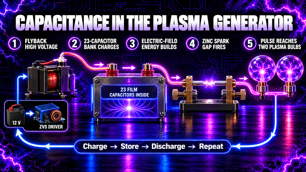
12 V DC supply → ZVS driver → flyback transformer → capacitor banks → adjustable zinc-rod spark gap → two plasma bulbs
The capacitor section sits between the high-voltage flyback output and the spark-gap/output network. Its behaviour can be understood as a repeating cycle.
Stage 1: The flyback supplies high voltage
The ZVS driver switches current in the flyback primary. The changing magnetic field induces high voltage in the secondary. The exact polarity and waveform depend on the flyback construction and circuit.
Stage 2: The capacitor banks accumulate charge
Current from the high-voltage source changes the charge on the capacitor-bank conductors. As charge accumulates, the bank voltage and stored electric-field energy rise.
Stage 3: The spark gap reaches breakdown
The electric field between the adjustable zinc rods increases with the gap voltage. When the field is sufficient to ionise the gas path, the gap changes rapidly from an insulating state to a conducting plasma channel.
Stage 4: Stored energy is released as a pulse
The conducting gap provides a low-impedance path relative to its open state. The capacitor network discharges rapidly into the output circuit. Peak pulse current can be much greater than the average charging current.
Stage 5: Capacitance and inductance produce ringing
Capacitance in the bank and inductance in the wiring, transformer, leads and output structure exchange energy. The pulse can become a damped high-frequency oscillation rather than a single smooth discharge.
Stage 6: The gap extinguishes and charging begins again
As energy is transferred and current falls, the plasma channel can extinguish. The capacitors then begin charging again, and the cycle repeats.
This repeated charge–breakdown–discharge cycle helps produce the broadband, pulsed character associated with a spark-gap system.
The 23-Capacitor Bank in Alan’s Generator
The documented design uses 23 WIMA film capacitors, each nominally 4.7 nF and 4 kV, physically organised as two groups of nine and one group of five.
Those component labels do not by themselves tell us the bank’s effective capacitance or reliable operating voltage. The answer depends on the exact PCB connections:
- capacitors connected in parallel add capacitance;
- capacitors connected in series reduce capacitance;
- a mixed network must be reduced section by section;
- real series strings need controlled voltage sharing;
- pulse voltage and current ratings must be respected;
- and board spacing must withstand the actual transient voltage.
If all 23 identical 4.7 nF capacitors were hypothetically connected in parallel, the ideal total would be:\[ 23 \times 4.7\ \text{nF} = 108.1\ \text{nF} \]
But that example does not describe the actual bank unless the PCB proves that all 23 devices share the same two nodes. Physical grouping alone is not an electrical schematic.
Likewise, adding printed voltage ratings is not enough to establish the safe bank rating. Tolerance, leakage, transient sharing, derating and insulation layout all have to be engineered.
Why Does the Spark Gap Need the Capacitor Bank?
The flyback charges the bank over a period of time. The spark gap then allows that accumulated energy to be delivered much more quickly.
This creates a useful distinction:
- the flyback provides energy at a limited rate;
- the capacitor bank stores part of that energy;
- the spark gap releases it in a short event;
- the output network shapes the resulting pulse and oscillation.
Without capacitance, the circuit would still contain stray capacitance, but it would not have the same deliberately controlled energy storage. Changing bank capacitance changes charging time, energy per cycle, resonant behaviour, pulse current and repetition pattern. It should never be altered without considering every affected rating.
Does More Capacitance Mean a Stronger Output?
Not automatically.
At a fixed voltage, greater capacitance stores more energy because \(U = \tfrac{1}{2}CV^2\). But increasing capacitance can also:
- lengthen charging time;
- reduce repetition rate;
- alter resonance;
- increase stress on the spark gap and wiring;
- increase peak discharge current;
- increase flyback loading;
- change losses and heating;
- and exceed component or insulation limits.
The result depends on the complete circuit. “More capacitance” is not a safe universal upgrade rule.
Capacitor Safety in High-Voltage Equipment
Capacitors can retain dangerous voltage after the power supply is disconnected. The absence of sound, light or visible plasma does not prove the bank is discharged.
Safe engineering may include:
- permanently fitted bleeder resistors;
- automatic discharge contactors or relays;
- interlocks;
- guarded and enclosed conductors;
- discharge indicators;
- clearly labelled test points;
- rated earthing or discharge tools;
- and a written isolate–discharge–verify procedure.
Bleeder resistors must be selected for resistance, voltage, pulse energy, continuous power, creepage and failure mode. A resistor with the correct resistance but inadequate voltage or power rating can fail dangerously.
Never discharge a high-voltage capacitor by touching its terminals together with a screwdriver. That uncontrolled method can create an arc, damage the capacitor, weld metal, eject molten material and leave residual charge.
Before work begins, the system should be isolated, prevented from being re-energised, discharged by the designed method and proved dead with suitable rated equipment. Recheck before touching because dielectric absorption or circuit conditions can allow voltage to return.
Common Myths About Capacitance
Myth 1: A capacitor stores current
It stores separated charge and electric-field energy. Current is the rate at which charge moves while the capacitor charges or discharges.
Myth 2: Capacitance is the same as charge
Capacitance describes charge per volt. The actual charge depends on both capacitance and voltage.
Myth 3: A larger capacitor always has a higher voltage rating
Physical size, capacitance and voltage rating are related through design, but one cannot be reliably inferred from another.
Myth 4: A 4 kV capacitor is safe on every 4 kV waveform
DC, AC, pulse, peak, RMS-current and frequency ratings differ. The manufacturer’s datasheet and derating rules control suitability.
Myth 5: Voltage ratings simply add in series
Only an ideal, equally sharing string divides voltage perfectly. Real strings can require balancing and transient control.
Myth 6: Parallel capacitors increase voltage rating
Parallel connection increases capacitance. Each capacitor still sees the full voltage across the two nodes.
Myth 7: A switched-off capacitor is safe
It may remain charged, recover voltage through dielectric absorption or be recharged through another circuit path.
Myth 8: A brief short circuit fully discharges every capacitor
A brief short can be destructive and may not prevent voltage recovery. Use a designed, current-limited discharge method and verify the result.
Myth 9: Capacitors pass AC straight through the dielectric
Charge does not normally conduct through an ideal dielectric. Alternating plate charge and electric-field change create the external circuit current.
Myth 10: More capacitance always improves a spark-gap generator
It changes stored energy, charge time, pulse current, resonance and component stress. The entire system must be redesigned and verified.
Frequently Asked Questions
What is capacitance in simple words?
Capacitance is how much separated charge a system stores for each volt between its conductors.
What is the difference between a capacitor and capacitance?
A capacitor is a physical component. Capacitance is the electrical property measured in farads.
What does one farad mean?
One farad means one coulomb of charge separation per volt: \(1\ \text{F}=1\ \text{C/V}\).
Can a capacitor have capacitance when it is uncharged?
Yes. Capacitance is a property of its geometry and dielectric. An uncharged capacitor has zero stored voltage and energy but still has its capacitance.
Does a capacitor create voltage?
No. A source or prior circuit action separates charge. Once charged, the capacitor can maintain a voltage temporarily and drive current while discharging.
Why does a capacitor block DC?
After an ideal capacitor has charged to a steady DC voltage, the voltage stops changing and \(I=C\,dV/dt\) becomes zero. Real capacitors retain a small leakage current.
Why can a capacitor carry AC current?
AC voltage continually changes, so charge continually moves onto and off the plates. Faster change produces more current for a given capacitance.
Which stores more energy: capacitance or voltage?
Both matter, but voltage is squared in \(U=\tfrac{1}{2}CV^2\). Doubling capacitance doubles energy at fixed voltage; doubling voltage quadruples it.
Do capacitors in parallel have the same voltage?
Yes. Ideal parallel capacitors share the same two nodes and therefore the same voltage.
Do capacitors in series have the same voltage?
Not necessarily. Ideal identical capacitors share equally, but different capacitances and real leakage can produce unequal voltage.
What happens if a capacitor exceeds its voltage rating?
The dielectric can break down, producing leakage, heating, arcing, permanent damage, short circuit, rupture or fire.
Why are film capacitors useful in pulse circuits?
Appropriately designed film capacitors can offer low loss, good stability and strong pulse performance. Suitability still depends on the exact series, construction and datasheet ratings.
What is a bleeder resistor?
A bleeder resistor is connected across a capacitor or bank to discharge it over time after power is removed. It must be correctly designed and does not remove the need to verify voltage.
What is the effective capacitance of the 23-capacitor bank?
It cannot be determined from the component count or physical groups alone. The complete PCB schematic is required to identify every series and parallel connection.
Can I measure the bank with a handheld multimeter?
Only after it has been safely isolated, discharged and verified, and only if the meter’s capacitance range suits the network. A handheld capacitance reading will not confirm high-voltage pulse suitability.
What Have We Learned?
Capacitance measures charge stored per volt:\[ C = \frac{Q}{V} \]
A capacitor separates equal and opposite charge on two conductors, with a dielectric between them. Its energy is stored in the electric field:\[ U = \frac{1}{2}CV^2 \]
Greater plate area, smaller separation and a higher-permittivity dielectric increase capacitance in the simple parallel-plate model. Real capacitors also have ESR, ESL, leakage, dielectric absorption and operating limits.
Parallel capacitors add capacitance and share the same voltage. Series capacitors reduce the equivalent capacitance and divide voltage, but real voltage sharing must be controlled rather than assumed.
In the plasma generator, the bank charges from the flyback and releases stored energy when the zinc-rod spark gap conducts. The resulting pulse interacts with circuit inductance to create high-frequency ringing. Because voltage is squared in the energy equation, high-voltage capacitors can remain dangerous even when their capacitance seems small.
🧠 Key Takeaways
- Capacitance is charge stored per volt.
- \(C=Q/V\) and \(1\ \text{F}=1\ \text{C/V}\).
- A capacitor has two conductors separated by a dielectric.
- Energy is stored in the capacitor’s electric field.
- Stored energy is \(U=\tfrac{1}{2}CV^2\).
- Doubling voltage quadruples stored energy at the same capacitance.
- Larger plate area and smaller spacing increase capacitance.
- A dielectric increases capacitance but has a breakdown limit.
- Capacitors in parallel add; capacitors in series combine reciprocally.
- Real series strings do not automatically share voltage equally.
- Capacitor current depends on how quickly voltage changes.
- At high frequency, ESR, ESL, layout and self-resonance matter.
- Component count does not reveal a bank’s effective capacitance.
- The plasma generator’s capacitor bank stores energy before each spark event.
- A disconnected capacitor can retain or recover dangerous voltage.
🔬 Capacitance Fact
If a capacitor’s voltage doubles while its capacitance stays the same, it stores twice the charge—but four times the energy. That square-law relationship is one of the most important facts in high-voltage capacitor safety.
Continue Your Learning Journey
Previous Lesson: Lesson 18 — What Is Electric Current?
Next Lesson: Lesson 20 — What Is Inductance? (Coming Soon)
Further Reading
- OpenStax, University Physics Volume 2: Capacitors and capacitance
- OpenStax, University Physics Volume 2: Capacitors in series and parallel
- OpenStax, University Physics Volume 2: Energy stored in a capacitor
- OpenStax, College Physics 2e: DC circuits containing resistors and capacitors
- UK Health and Safety Executive: High-voltage isolation and stored-energy safety
Learn More About High-Frequency Plasma
Explore the complete High Frequency Plasma Learning Centre at HighFrequencyPlasma.com.
For project updates and discussion, join the Telegram community: https://t.me/HighFrequencyPlasma
Disclaimer
This lesson is for general educational purposes. High-voltage capacitors and capacitor banks can cause fatal electric shock, severe burns, arc flash, fire, component rupture and injury from stored energy even after the power supply is disconnected.
Do not construct, alter, open, discharge, probe or operate high-voltage equipment unless you are competent to do so and have appropriate isolation, enclosures, interlocks, discharge systems, protective equipment and correctly rated test instruments. Never rely on an open switch, a stopped spark gap, a bleeder resistor or a previous voltage reading as the sole proof that a capacitor is safe.
This plasma generator is not medical equipment and is not intended to diagnose, treat, cure or prevent any condition. Do not use it if you are pregnant or have a pacemaker or other implanted electronic device. Keep it away from sensitive electronics and follow all applicable electrical-safety requirements.
🎉 Lesson Complete
You now understand what capacitance is, how capacitors store charge and energy, how series and parallel banks behave, and why capacitor ratings and safe discharge procedures are essential in a spark-gap plasma generator.
In Lesson 20, we will study inductance: how changing current creates magnetic flux, why inductors oppose changes in current, how coils store magnetic-field energy, and how inductance works with capacitance to produce resonance.