
How Does a Transformer Work? A transformer transfers electrical energy between circuits through a changing magnetic field. It can raise voltage, lower voltage, change available current, match impedance or provide electrical isolation—all without a direct conductive connection between its primary and secondary windings.
Lesson 21 of 24 — High Frequency Plasma Learning Centre
Transformers range from huge grid units to tiny high-frequency components. The High Frequency Plasma generator uses a flyback transformer: the 12 V supply powers a ZVS driver, the driver switches current through the flyback primary, and changing magnetic flux induces high voltage in the secondary.
This lesson explains how a transformer works, what its primary, secondary and core do, how turns ratio affects voltage and current, why transformers need changing current, where energy losses occur and how transformer action fits into the plasma generator.
What You’ll Learn About How Does a Transformer Work
By the end of this lesson, you will understand:
- how mutual induction transfers energy;
- the jobs of the primary, secondary and magnetic core;
- why changing magnetic flux is essential;
- how turns ratio determines ideal voltage ratio;
- why increasing voltage reduces available current for similar power;
- the difference between step-up, step-down and isolation transformers;
- why steady DC can overheat a conventional transformer;
- what flux leakage, copper loss, core loss and saturation mean;
- why high-frequency transformers can be compact;
- and how the flyback transformer works within the plasma-generator chain.
The Short Answer: How Does a Transformer Work?
A transformer works in four basic steps:
- changing current flows in the primary winding;
- the primary produces changing magnetic flux in the core;
- that changing flux links the secondary winding;
- Faraday’s law causes a voltage to be induced across the secondary.
For a secondary with \(N_s\) turns:\[ V_s=-N_s\frac{d\Phi}{dt} \]
The minus sign represents Lenz’s law: the induced voltage has a polarity that opposes the change responsible for it.
A transformer does not mechanically send electrons from the primary wire into the secondary wire. Energy crosses through the electromagnetic field. The windings can therefore be electrically isolated while remaining magnetically coupled.
The Main Parts of a Transformer
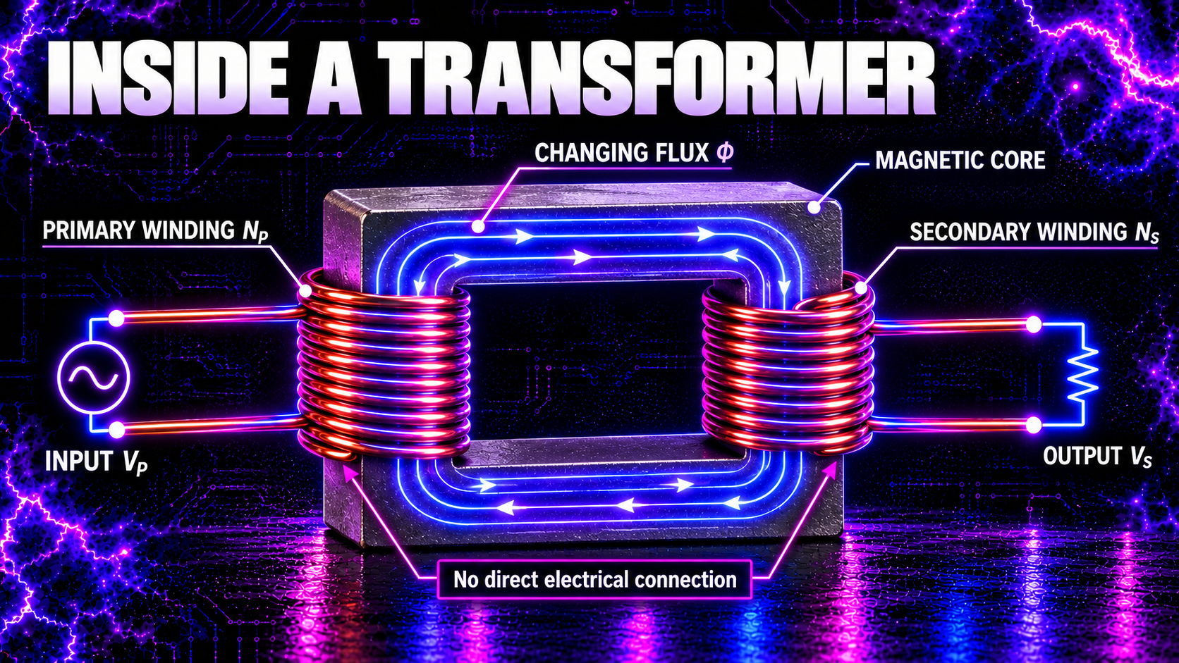
Primary winding
The primary is connected to the input source. Its changing current creates magnetic flux. The number of primary turns is written \(N_p\).
Secondary winding
The secondary supplies the transformed output. Changing core flux induces voltage across its \(N_s\) turns. Connecting a load allows secondary current to flow.
Magnetic core
The core provides a controlled path for magnetic flux and helps both windings share that flux. Low-frequency transformers often use laminated electrical steel. High-frequency transformers commonly use ferrite because its high electrical resistance helps limit eddy-current loss.
Insulation and bobbin
Insulation separates turns, windings, core and accessible parts. In high-voltage transformers, insulation structure, creepage, clearance and winding arrangement are fundamental safety and reliability features—not cosmetic details.
Why Must the Magnetic Flux Change?
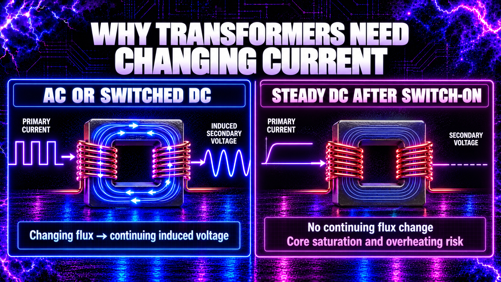
Faraday’s law depends on the rate of change of magnetic flux. Constant flux produces no continuous induced secondary voltage.
With AC, the primary current and core flux repeatedly change direction. With a switching converter, transistors turn primary current on, off or between paths, also creating changing flux. Either method can drive transformer action when the core and windings are designed for that waveform.
If steady DC is applied directly to a conventional transformer primary, there is only a brief changing-flux event during switch-on. Afterward, the ideal inductive opposition disappears. Current is then limited mainly by winding resistance, and the core may saturate. Excessive current, overheating or failure can follow.
This is why the generator’s 12 V DC supply does not feed the flyback winding as unchanging DC. The ZVS driver converts it into rapidly changing primary current.
What Is Mutual Inductance?
The transformer is a practical application of mutual inductance. A change of current in one circuit creates changing magnetic flux that links another circuit and induces an emf there.
For two coils:\[ V_s=-M\frac{dI_p}{dt} \]
where \(M\) is mutual inductance.
Mutual inductance depends on the number of turns, core properties, coil geometry and how much primary flux links the secondary. A coupling coefficient, usually written \(k\), describes how tightly the windings are coupled. Perfect coupling would mean \(k=1\), but real transformers always have some leakage flux.
The portion of flux that does not link both windings contributes to leakage inductance. Leakage can create voltage spikes, reduce regulation or participate in intentional resonant behaviour.
What Is the Transformer Turns Ratio?
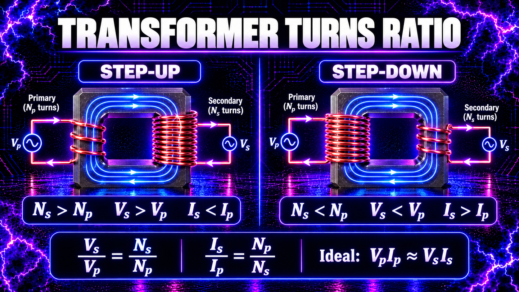
In an ideal transformer, both windings experience the same changing core flux per turn. The voltage ratio therefore equals the turns ratio:\[ \frac{V_s}{V_p}=\frac{N_s}{N_p} \]
If the secondary has more turns than the primary, the transformer steps voltage up. If it has fewer turns, it steps voltage down.
For example, an ideal transformer with 20 primary turns and 200 secondary turns has a 1:10 turns ratio. An input of 12 V AC would correspond to 120 V AC under ideal assumptions.
Real output depends on waveform, frequency, load, losses, winding resistance, coupling and core behaviour. The simple turns-ratio calculation is a starting point, not a guaranteed measured result—especially for pulsed flyback circuits.
How Does Current Change Through a Transformer?
An ideal transformer conserves power:\[ V_pI_p=V_sI_s \]
Combining this with the turns ratio gives:\[ \frac{I_s}{I_p}=\frac{N_p}{N_s} \]
Voltage and current ratios therefore move in opposite directions:
- step voltage up and the available current steps down;
- step voltage down and the available current steps up.
A transformer does not multiply power. Real output power is lower than input power because energy is lost as heat, sound, leakage flux and electromagnetic radiation.
The current actually drawn also depends on the load. A secondary rated for 1 A does not force 1 A into every connected device. The connected load and transformer impedances determine current within the design limits.
Step-Up, Step-Down and Isolation Transformers
Step-up transformer
A step-up transformer has more secondary turns than primary turns. It raises voltage and correspondingly reduces available current for similar power.
Step-down transformer
A step-down transformer has fewer secondary turns. It lowers voltage and permits greater secondary current, again subject to winding and power limits.
Isolation transformer
An isolation transformer may have a 1:1 turns ratio. Its purpose is not necessarily to change voltage but to separate circuits galvanically.
Isolation can reduce some hazards and break certain earth-referenced paths, but it does not make the secondary safe to touch. Contact across both secondary conductors can still be fatal, and stray capacitance can couple high-frequency current across the isolation barrier.
What Happens When a Load Is Connected?
With the secondary open, the primary still draws a small magnetising current to establish flux and supply core losses. This is the no-load condition.
When a load is connected, secondary current creates its own magnetic effect opposing the change that produced it. The primary then draws additional current from the source so that the core flux remains close to its operating value and energy is transferred to the load.
The primary therefore “feels” the secondary load through magnetic coupling. A short circuit on the secondary can demand dangerously high current on both sides unless impedance, current limiting or protection intervenes.
Why Are Transformers Rated in VA?
Transformers are commonly rated in volt-amperes (VA) rather than watts because winding heating depends largely on current while insulation and core flux depend on voltage and frequency. Some loads draw current out of phase with voltage, so apparent power \(VA\) can exceed real power in watts.
For a simple sinusoidal single-phase rating:\[ S=V_{\text{RMS}}I_{\text{RMS}} \]
Waveforms from switching and spark-gap circuits may not be sinusoidal. Peak voltage, peak current, RMS current, duty cycle, frequency spectrum and insulation stress must all be considered.
What Causes Transformer Losses?
No real transformer is perfectly efficient.
Copper loss
Winding resistance produces \(I^2R\) heating. Thinner wire, longer windings and higher RMS current increase this loss.
Hysteresis loss
The core’s magnetic domains repeatedly reverse as flux changes. This consumes energy and heats the core.
Eddy-current loss
Changing flux induces circulating currents inside conductive core material. Laminated steel or electrically resistive ferrite helps reduce these currents.
Leakage flux
Not all primary flux links the secondary. Leakage inductance reduces ideal coupling and can create switching transients.
Winding capacitance
Adjacent turns and windings form unintended capacitors. At high frequency, this capacitance alters resonance and can couple interference across the transformer.
Mechanical and radiated loss
Magnetostriction can cause audible hum. Some energy also leaves as stray electromagnetic fields.
What Is Core Saturation?
Core flux density cannot increase indefinitely. When the core approaches saturation, additional magnetising current produces relatively little extra flux. Effective primary inductance falls and current can rise sharply.
Saturation may result from:
- too few primary turns;
- excessive applied voltage;
- frequency that is too low;
- excessive switch-on time;
- a DC bias or unbalanced drive;
- unsuitable core material;
- or excessive temperature.
Symptoms can include overheating, high supply current, distorted waveforms and transistor failure. Adding a larger fuse does not solve saturation; the magnetic design and drive conditions must be corrected.
Why Can High-Frequency Transformers Be Smaller?
Faraday’s law shows that induced voltage depends on how quickly flux changes. At higher frequency, more flux-change cycles occur each second, so a transformer can often transfer a given power with a smaller core and fewer turns than a 50 Hz unit.
This advantage has limits. Higher frequency increases switching loss, skin and proximity effects, dielectric loss, electromagnetic interference and sensitivity to stray capacitance and inductance. Core material must suit the operating frequency.
This is why a compact ferrite flyback can produce high voltage at kilohertz-range switching while a mains transformer handling comparable power may be much larger.
Transformer Polarity and Dot Convention
Schematic dots indicate the relative instantaneous polarity of coupled windings. If current enters the dotted end of one winding, the induced voltage makes the dotted end of the other winding positive under the stated reference convention.
Polarity matters when windings are connected in series, parallel, push-pull or centre-tapped arrangements. Reversing a winding can make induced voltages add or subtract. In a switching converter, incorrect phasing can prevent operation or damage components.
Wire colours and physical position are not universal proof of polarity. Use manufacturer data or controlled testing with suitable equipment.
Is a Flyback a Normal Transformer?
A flyback uses magnetic coupling, but its operating cycle differs from an ordinary transformer carrying energy simultaneously from primary to secondary.
In a classic flyback converter:
- a switch drives current in the primary;
- energy is stored mainly in the gapped magnetic core;
- the switch turns off;
- winding polarity reverses;
- stored energy is delivered through the secondary.
Television-style flybacks may include rectification, multiple windings and construction intended for very high voltage. When driven by a ZVS or resonant circuit, the exact waveform depends on the driver, winding arrangement, core, internal diodes and load. It should not be assumed to match a simple textbook sine-wave transformer.
Lesson 22 will examine flyback operation in detail.
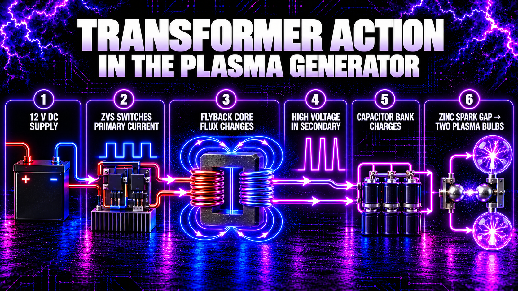
The Transformer in the High Frequency Plasma Generator
The generator uses this chain:
12 V DC supply → ZVS driver → flyback transformer → capacitor banks → adjustable zinc-rod spark gap → two plasma bulbs
Stage 1: The ZVS driver creates changing current
The regulated 12 V supply provides DC, but the ZVS driver switches it through the flyback primary. This creates rapidly changing current and magnetic flux.
Stage 2: The core couples the windings
Primary flux travels through the ferrite core. The portion linking the secondary induces high voltage according to Faraday’s law and the flyback’s construction.
Stage 3: Voltage rises while current capability falls
The secondary has many turns relative to the added primary drive winding. It produces high voltage with much lower current capability than the 12 V side. Exact output cannot be calculated safely from turns ratio alone because the waveform, coupling, load and internal flyback structure matter.
Stage 4: The capacitor banks charge
The high-voltage output transfers energy into the capacitor network. Bank voltage rises until conditions allow the spark gap to break down.
Stage 5: The spark gap releases a pulse
The zinc-rod gap becomes conductive and releases stored capacitor energy into the output network. Capacitance and inductance create a damped high-frequency ringing waveform that excites the two plasma bulbs.
The flyback therefore provides the magnetic link between the low-voltage switching stage and the high-voltage charging stage.
How Are Transformers Tested?
Common checks include winding continuity, resistance, insulation resistance, turns ratio, inductance, leakage inductance and waveform measurements.
An LCR meter or turns-ratio tester can examine an unpowered transformer. An oscilloscope can show primary and secondary waveforms only when used with correctly rated isolated, differential or high-voltage probes.
Never use an ordinary multimeter or oscilloscope probe on a flyback output unless its voltage, frequency, energy and measurement category are appropriate. The oscilloscope ground clip may be connected to protective earth and can short a live or floating node.
Transformer Safety
High-voltage transformers can produce shock, burns, arcs, fire and insulation failure. The connected capacitor bank can remain charged after power is removed.
Safe practice includes:
- using the correct supply, fuse and enclosure;
- isolating and securing power before inspection;
- discharging stored energy through a designed system;
- proving conductors dead with suitable rated equipment;
- maintaining creepage, clearance and insulation barriers;
- keeping wiring away from sharp edges, heat and moving fans;
- and stopping use if there are burn marks, cracking, unusual noise or overheating.
An RCD is secondary protection and does not make a high-voltage secondary safe. The generator is not medical equipment. Do not use it if you are pregnant or have a pacemaker or other implanted electronic device, and keep it away from sensitive electronics.
Common Myths About Transformers
Myth 1: A transformer creates power
It transforms voltage and current while transferring energy. Output power cannot exceed input power.
Myth 2: More secondary turns always mean a safe output
More turns can raise voltage, but insulation, current, core behaviour and loading determine whether the design is safe.
Myth 3: A transformer works on steady DC
Steady DC produces no continuous changing flux. A switching circuit is required.
Myth 4: The primary and secondary are completely unrelated
They may be conductively isolated, but they are linked magnetically and also have stray capacitive coupling.
Myth 5: A transformer’s rated current is forced into the load
The load determines the current drawn within the transformer’s capability.
Myth 6: Turns ratio predicts every flyback voltage
It is an ideal starting point. Switching waveform, internal rectification, coupling, leakage and load also matter.
Frequently Asked Questions
How does a transformer work in simple words?
Changing current in the primary creates changing magnetic flux, which induces voltage in the secondary.
Does electricity pass through the core?
No. The core guides magnetic flux. Electrical current remains in the windings unless insulation fails.
What controls secondary voltage?
Primarily the input waveform, turns ratio and changing flux, with real output also affected by losses and load.
Why does a step-up transformer have lower output current?
Because power is approximately conserved. Raising voltage requires lower current for similar transferred power.
Can a transformer change frequency?
An ordinary transformer transfers the applied waveform frequency. It does not normally create a new fundamental frequency, although distortion and switching can introduce harmonics.
Does isolation make the output safe?
No. It removes a direct conductive path but hazardous voltage can still exist between secondary conductors or through stray coupling.
Why does a transformer get hot?
Winding resistance, core hysteresis, eddy currents, stray losses or overload convert energy into heat.
Why does the plasma generator need a ZVS driver?
The flyback requires changing primary current. The ZVS driver converts the 12 V DC supply into a rapidly changing drive waveform.
Can the flyback output be predicted from turns ratio alone?
Not reliably. The internal winding, diodes, waveform, frequency, coupling and load must also be known.
What Have We Learned?
A transformer transfers energy through changing magnetic flux and mutual inductance. Its ideal voltage ratio is:\[ \frac{V_s}{V_p}=\frac{N_s}{N_p} \]
Its ideal current ratio moves in the opposite direction, so voltage can rise only as available current falls for similar power.
In the plasma generator, the ZVS driver creates the changing current that the flyback needs. The flyback then couples energy from the low-voltage primary side to the high-voltage secondary side, charging the capacitor banks before the spark gap releases each pulse.
🧠 Key Takeaways
- Transformers work through changing magnetic flux.
- The input winding is the primary; the output winding is the secondary.
- Mutual inductance links the two circuits.
- Voltage ratio ideally equals turns ratio.
- Current ratio changes inversely to voltage ratio.
- A transformer does not create power.
- Steady DC cannot continuously operate a conventional transformer.
- Core saturation can cause destructive current.
- Real transformers have copper, core and leakage losses.
- High frequency allows smaller magnetic components but increases parasitic effects.
- Isolation does not make a high-voltage secondary safe.
- The ZVS driver supplies changing current to the plasma generator’s flyback.
Continue Your Learning Journey
Previous Lesson: Lesson 20 — What Is Inductance?
Next Lesson: Lesson 22 — How Does a Flyback Transformer Work? (Coming Soon)
Further Reading
- OpenStax, College Physics 2e: Transformers
- OpenStax, University Physics Volume 2: Mutual inductance
- UK Health and Safety Executive: Safe use of electrical equipment
Learn More About High-Frequency Plasma
Explore the complete High Frequency Plasma Learning Centre at HighFrequencyPlasma.com.
Join the Telegram community: https://t.me/HighFrequencyPlasma
Disclaimer
This lesson is for general educational purposes. High-voltage transformers can cause fatal electric shock, severe burns, fire, component rupture and electromagnetic interference. Connected capacitors may retain dangerous energy after power is removed.
Do not construct, open, alter, probe or operate high-voltage equipment unless you are competent and have suitable isolation, enclosures, interlocks, discharge systems and correctly rated test instruments. This generator is not medical equipment and is not intended to diagnose, treat, cure or prevent any condition.
🎉 Lesson Complete
You now understand how primary current creates magnetic flux, how the secondary receives energy through mutual induction and why a flyback can transform low-voltage switching into high voltage.
In Lesson 22, we will explore the flyback transformer in detail, including energy storage, primary switching, core gaps, high-voltage output and the generator’s specific drive arrangement.