
How does a flyback transformer works? A flyback transformer can turn a low-voltage switching waveform into a much higher voltage. Although it resembles an ordinary transformer, it is designed to handle pulsed energy, rapid changes in magnetic flux and—in many applications—temporary energy storage within a gapped magnetic structure.
Lesson 22 of 24 — High Frequency Plasma Learning Centre
The High Frequency Plasma generator uses a flyback taken from the world of cathode-ray-tube electronics. A 12 V DC supply powers a ZVS driver, the driver produces rapidly changing current in an added primary winding, and the flyback’s high-turn secondary generates the voltage that charges the capacitor banks.
This lesson explains how a flyback transformer works, why its core is normally gapped, what happens during the switch-on and switch-off periods, how a ZVS driver excites it and why its real output cannot be calculated from turns ratio alone.
What You’ll Learn
By the end of this lesson, you will understand:
- why a flyback is often described as a coupled inductor;
- how it differs from an ordinary transformer;
- what happens during the energy-storage and energy-delivery phases;
- why winding polarity and rectifier direction matter;
- how primary inductance and peak current determine stored energy;
- why the ferrite core usually contains a non-magnetic gap;
- the meaning of continuous, discontinuous and critical conduction;
- how leakage inductance creates voltage spikes and ringing;
- how a television flyback produces a high-voltage output;
- and how the ZVS-driven flyback fits into the plasma generator.
The Short Answer: How Does a Flyback Transformer Work?
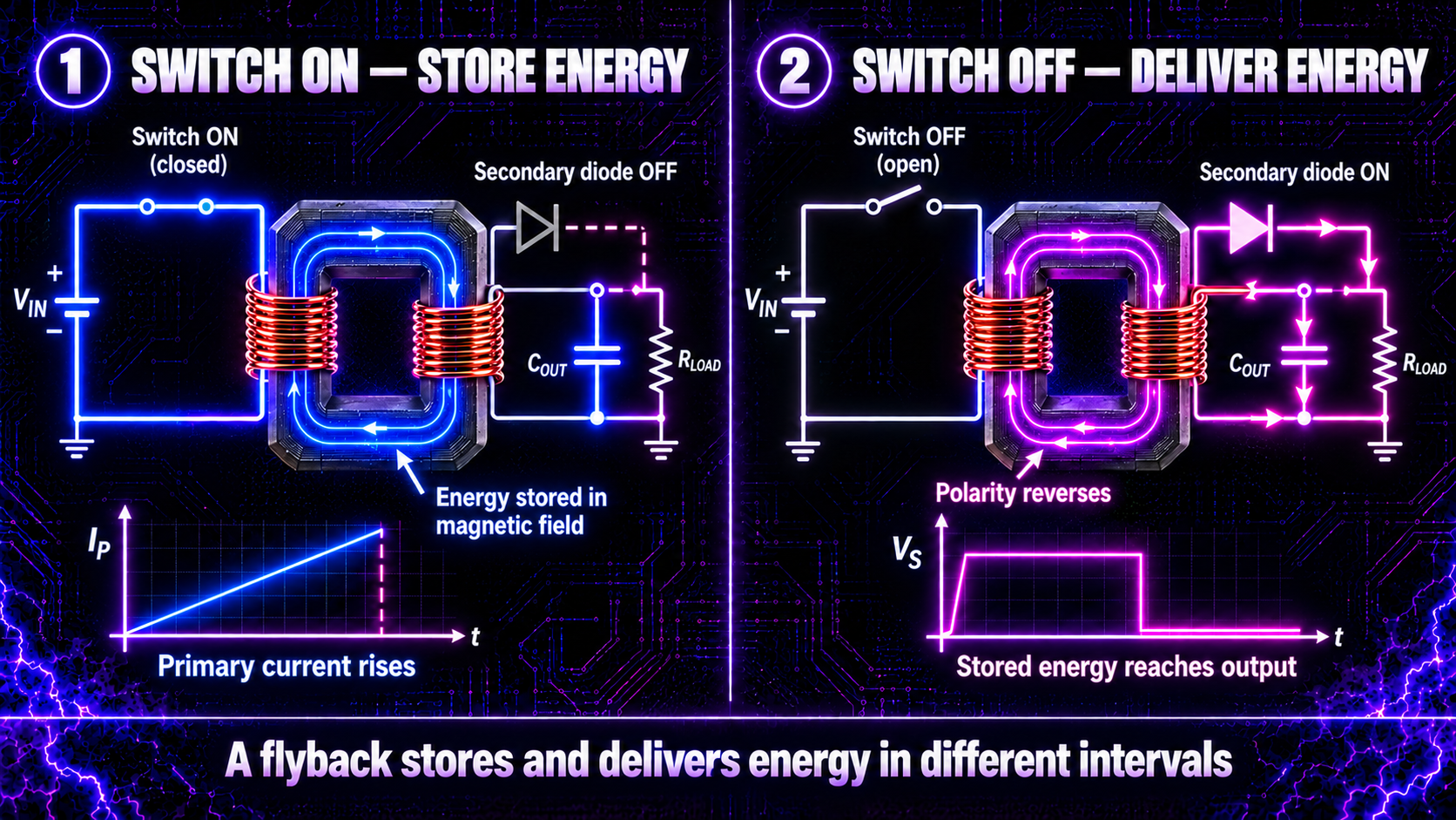
In the classic flyback-converter cycle, a switch first connects the input supply to the primary winding. Primary current rises and energy builds in the magnetic field. Winding polarity keeps the secondary rectifier off during this interval.
When the switch opens, the magnetic field begins to collapse. The voltage across every winding reverses polarity, the secondary rectifier conducts and stored magnetic energy flows into the output capacitor and load.
The two essential phases are therefore:
- Switch on: store energy through the primary.
- Switch off: release energy through the secondary.
Unlike an ordinary transformer, the classic flyback does not primarily transfer energy to the secondary while the input switch is on. It stores and delivers energy in alternating time intervals.
Why Is It Called a Flyback?
The term came from cathode-ray-tube television circuits. At the end of each scanned line, the horizontal deflection current had to return—or “fly back”—quickly. Its rapid collapse produced a pulse that a specialised transformer used to generate the CRT’s high voltage. Modern switching supplies use the same magnetic principle without a display.
A “29-inch flyback” normally describes the television size or application family for which the component was designed. It does not mean that the transformer itself is 29 inches long.
Flyback Transformer or Coupled Inductor?
An ordinary transformer ideally transfers energy from primary to secondary at the same moment. A flyback magnetic component behaves more like an inductor with additional coupled windings.
When primary current rises, its magnetising inductance stores energy:\[ E=\frac{1}{2}L_m I_{pk}^{2} \]
where:
- \(E\) is stored energy;
- \(L_m\) is primary magnetising inductance;
- and \(I_{pk}\) is peak primary current.
Because current is squared, a modest rise in peak current produces much more stored energy—and substantially greater heating and semiconductor stress.
The windings remain magnetically coupled, so the turns ratio still affects voltage and current. However, inductance, switching time, duty cycle, rectification, load, leakage and core behaviour all influence the final output.
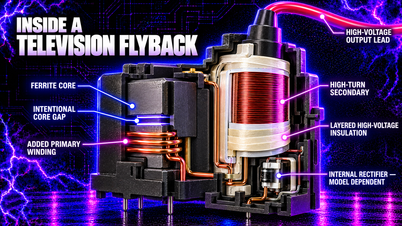
The Main Parts of a Flyback Transformer
Ferrite core
Ferrite provides a low-loss path for rapidly changing flux at much higher frequencies than traditional laminated-steel cores.
Non-magnetic core gap
A small non-magnetic gap raises reluctance. It reduces inductance for a given winding but allows useful energy storage without saturating as quickly. Most recoverable field energy is associated with the gap.
Primary winding
The primary receives switched or alternating current from the driver. In Alan’s plasma generator, a balanced, tightly wound drive coil is added around the exposed ferrite core.
High-voltage secondary
The secondary contains many turns of fine, carefully insulated wire. Its layers must withstand substantial voltage differences without internal arcing.
Rectifier and output network
Many later television flybacks contain high-voltage rectifiers, and some contain focus or screen-divider components. Construction varies, so never assume the internal circuit from appearance.
Encapsulation and high-voltage lead
Resin, plastic and insulation barriers prevent adjacent winding layers and external parts from breaking down. The thick high-voltage lead carries the output away from the secondary.
Phase One: The Primary Stores Energy
When the primary switch conducts, the input voltage appears across the primary magnetising inductance. Primary current begins to rise. In a simplified linear region:\[ \frac{dI_p}{dt}=\frac{V_{in}}{L_m} \]
A higher input voltage, lower inductance or longer on-time produces greater peak current.
The polarity dots and output-diode direction are chosen so that the secondary rectifier is reverse biased during this interval. The output load is therefore supplied temporarily by its output capacitor in a conventional regulated flyback supply.
If the switch stays on too long, the core can approach saturation. Primary inductance then falls and current can rise destructively. Correct current limiting, timing and magnetic design are essential.
Phase Two: The Secondary Receives Energy
When the primary switch opens, inductor current cannot stop instantaneously. The magnetic field begins to collapse and the winding voltages reverse polarity.
This reversed secondary voltage forward biases the rectifier. Current now flows through the secondary into the output capacitor and load. As stored energy is delivered, secondary current falls.
Output voltage is influenced by:
- input voltage, primary inductance and peak current;
- winding turns, resistance and coupling;
- switching frequency and timing;
- rectification and output capacitance;
- core loss, saturation and the connected load.
This is why measuring a few winding turns and applying the ordinary transformer turns-ratio equation cannot reliably predict a flyback’s high-voltage output.
Why Does a Flyback Need a Core Gap?
High-permeability ferrite guides flux efficiently, but an ungapped core reaches saturation with relatively little magnetising force. A gap makes the magnetic circuit less permeable and lets it support a larger DC-biased current swing.
The gap is an energy-storage feature, not a defect. It makes inductance more predictable and permits more recoverable energy before saturation.
A larger gap is not automatically better. Increasing it usually requires more winding turns for the intended inductance, increases fringing fields and may raise copper loss. Flyback design is a balance between inductance, peak current, stored energy, flux density, winding space, efficiency and temperature.
Never alter the factory core gap casually. Grinding, shimming or clamping ferrite changes the magnetic design and can cause failure.
What Do Turns Ratio and Duty Cycle Do?
Turns ratio determines how primary voltage is reflected to the secondary and how secondary voltage is reflected back to the switch. In an ideal, regulated flyback operating under simplified continuous conditions:\[ \frac{V_o}{V_{in}}\approx\frac{N_s}{N_p}\frac{D}{1-D} \]
Here \(D\) is switch duty cycle. Real circuits must also account for diode drops, losses, leakage, winding resistance, control method and load.
For a television flyback driven by a resonant ZVS circuit, this equation is not a reliable output calculator. The waveform is not a simple fixed-duty PWM waveform, the secondary may contain internal diodes and capacitances, and the high-voltage load can be highly non-linear.
More secondary turns can increase voltage, but insulation and parasitic capacitance impose practical limits. More primary turns usually increase inductance and reduce current rise, while too few turns can push the core towards saturation.
DCM, CCM and Critical Conduction
Flyback converters can operate in several current modes:
- Discontinuous conduction mode (DCM): all stored energy is delivered and secondary current reaches zero before the next cycle. Peak current is often higher.
- Continuous conduction mode (CCM): some energy remains when the next cycle begins. Peak current may be lower for the same average power, but control is more demanding.
- Critical or transition mode (CrM): the next primary cycle begins just as secondary current reaches zero—the boundary between DCM and CCM.
These terms describe a classic converter’s magnetising current. A self-oscillating ZVS flyback driver has resonant current waveforms and should not be forced into a simple DCM-or-CCM description without measurements.
Leakage Inductance, Spikes and Ringing
Not all primary flux links the secondary. The unshared portion appears as leakage inductance. When primary current is interrupted, energy trapped in that leakage inductance cannot immediately reach the secondary.
It can produce a sharp voltage spike across the switching device. Leakage inductance also resonates with winding capacitance, diode capacitance and transistor capacitance, producing ringing and electromagnetic interference.
Commercial converters use winding techniques, clamps and snubbers to control these effects. Although oscillation is part of the plasma system’s behaviour, uncontrolled spikes can still destroy MOSFETs or insulation.
Short, well-arranged current paths, appropriate component ratings, balanced drive windings and effective cooling all matter. Merely installing a higher-current fuse does not protect a semiconductor from nanosecond or microsecond overvoltage events.
How Does a ZVS Driver Power the Flyback?
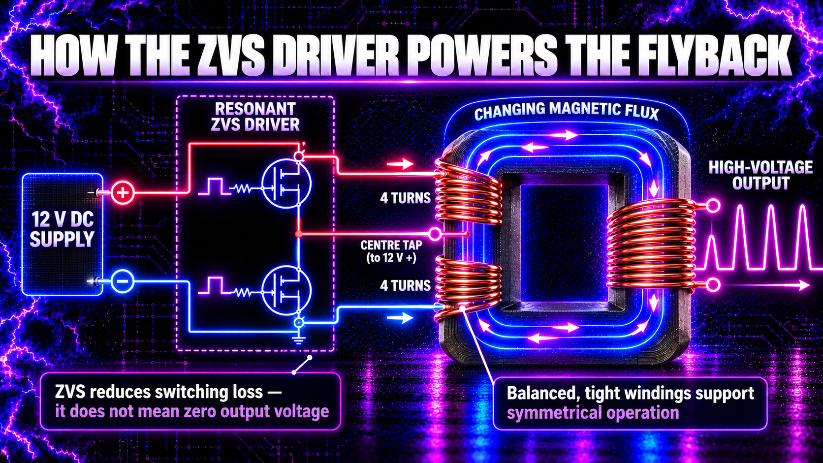
The plasma generator’s ZVS stage is not identical to the textbook single-switch flyback converter. It is a self-oscillating resonant driver that creates alternating high-frequency current in an added primary winding.
In a common centre-tapped arrangement, the two halves of the primary have equal turns. The centre connection receives the positive supply while the switching transistors alternately pull the outer ends. The resonant network encourages each transistor to change state when its voltage is near zero—hence zero-voltage switching.
This reduces switching loss compared with forcing a transistor to switch while both voltage and current are high. It does not mean the circuit has zero voltage, zero current or zero heat.
For Alan’s established build, the two drive sections use four tight turns each. Equal turn counts and similar physical placement help keep the magnetic drive balanced. A loose winding, missing turn or object separating one section from the core changes inductance and coupling and can cause unequal transistor stress.
Because the current alternates, core flux continually changes. The original high-turn secondary responds with a much larger voltage waveform. Internal rectification, when present, converts that waveform into high-voltage pulses of one polarity.
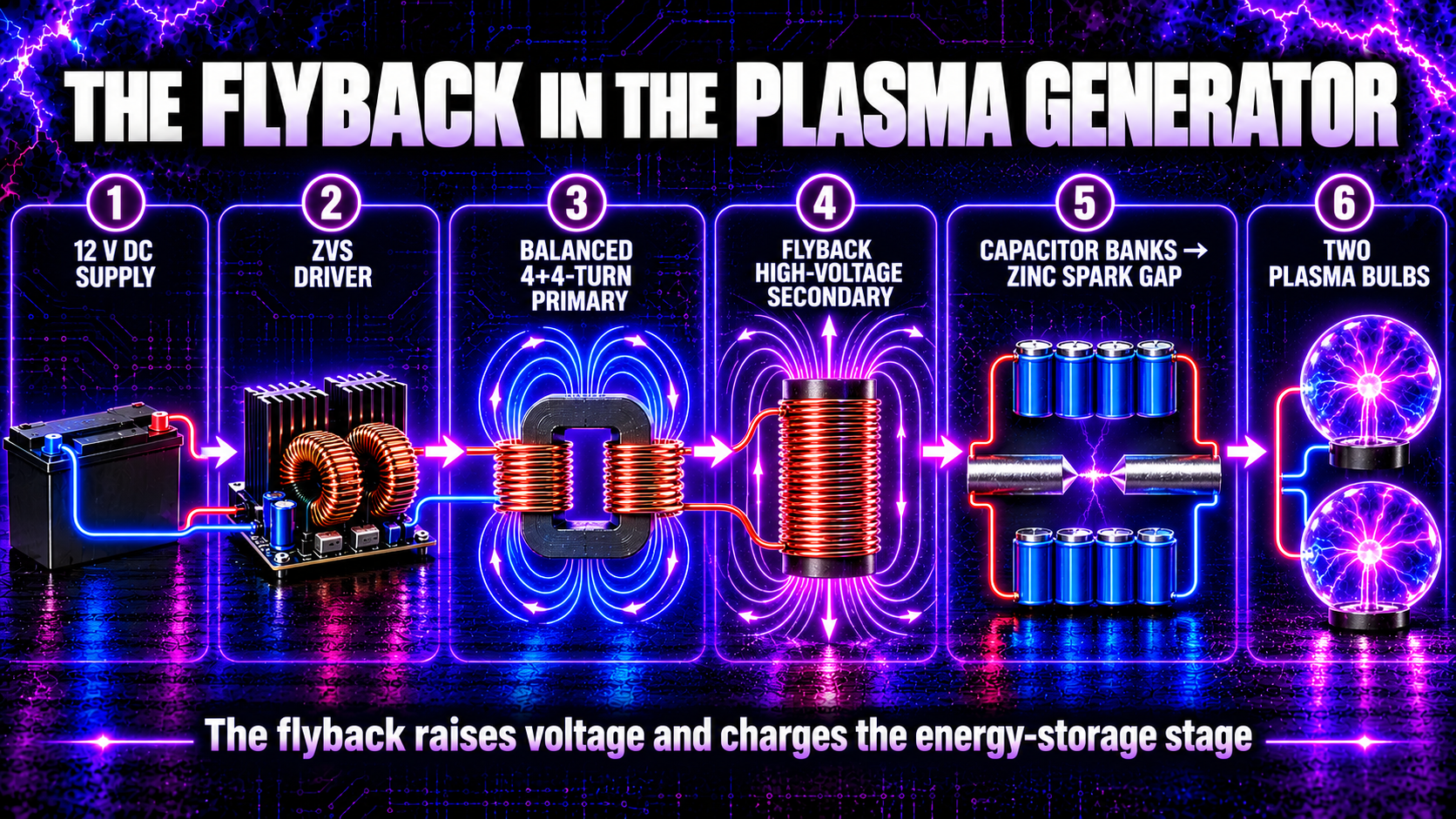
The Flyback in the High Frequency Plasma Generator
The complete energy path is:
12 V DC supply → ZVS driver → 4+4-turn flyback drive winding → high-voltage secondary → capacitor banks → adjustable zinc-rod spark gap → two plasma bulbs
1. The supply provides low-voltage current
The 12 V supply is the energy source. The flyback does not create energy; it changes the voltage, current and timing with which energy is delivered.
2. The ZVS stage produces rapid current changes
The driver alternately excites the balanced primary sections. The resonant current creates changing magnetic flux in the ferrite core.
3. The secondary generates high voltage
The high-turn secondary develops a much greater voltage with much lower current capability than the primary side. Exact voltage varies with supply, tuning, coupling, spark-gap loading and the individual flyback.
4. The capacitor banks accumulate energy
High-voltage pulses charge the capacitor network. The capacitors separate the slower charging interval from the much faster discharge event.
5. The spark gap switches the stored energy
When the electric field across the zinc rods becomes strong enough, the air ionises and the gap conducts. Stored energy is released into the output network.
6. The output rings at high frequency
The capacitor-bank capacitance and circuit inductance form an oscillatory network. Each spark initiates a damped burst containing a range of frequency components, energising the two plasma bulbs.
The flyback’s job is therefore not to power the bulbs directly as though they were an ordinary load. It raises voltage and charges the energy-storage stage that feeds the spark-gap pulses.
Why Does the Output Change Under Load?
An unloaded output can rise until losses, parasitic effects, corona or insulation limit it. A load removes energy on every cycle, so voltage usually falls.
Spark gaps are especially non-linear loads. Before breakdown, the gap draws little current while the capacitor voltage rises. During breakdown, its impedance drops abruptly and the capacitor bank discharges. The flyback then begins charging the bank again.
Gap distance affects firing voltage, repetition and charging-system stress; it does not simply “turn up the frequency.” Rod condition, humidity, electrode geometry and capacitance also matter.
Common Flyback Failure Causes
Typical causes include:
- an incorrect or unbalanced primary winding;
- excessive supply voltage or current;
- core saturation;
- poor cooling;
- internal secondary breakdown;
- damaged high-voltage insulation;
- excessive leakage-inductance spikes;
- operating without an appropriate load or protection;
- arcing to nearby metalwork;
- and incorrect pin or polarity identification.
Stop for cracking, carbon tracks, melted resin, unintended corona, unstable arcing or rapidly rising current. Do not trust a unit that has flashed over internally simply because it works after cooling.
How Can a Flyback Be Tested?
Unpowered checks include visual inspection, continuity, resistance, inductance and ring testing. A ring tester applies a small pulse; shorted turns damp the resulting oscillation quickly.
Powered measurements require appropriately rated high-voltage probes, differential or isolated methods and an understanding of instrument grounding. An ordinary oscilloscope earth clip can short a floating node to protective earth and destroy the circuit or injure the operator.
Never judge output solely by arc length. It also depends on electrode shape, humidity, repetition rate, current and waveform. Compare controlled measurements with a known-good unit.
Flyback Safety
A flyback system can cause fatal electric shock, burns, deep tissue injury, fire, component rupture and electromagnetic interference. Its output can also charge nearby capacitance unexpectedly.
The capacitor banks may retain dangerous energy after the 12 V supply is disconnected. Use a designed discharge path, enclosure, interlocks, current protection, strain relief, adequate clearance and correctly rated insulation. Keep one hand away from the equipment during permitted diagnostic work and never rely on that convention as a substitute for isolation and proving dead.
Do not operate the generator near TVs, laptops, computers, phones or other sensitive electronics. It is not medical equipment. Do not use it if pregnant or if you have a pacemaker or another implanted electronic device.
Construction, modification and live testing should be undertaken only by a competent person familiar with high-voltage and high-frequency hazards.
Common Myths About Flyback Transformers
Myth 1: A flyback is just a normal step-up transformer
It uses transformer action, but classic flyback operation deliberately stores and releases magnetic energy in separate intervals.
Myth 2: The air gap means the core is damaged
The gap is normally intentional and enables controlled energy storage.
Myth 3: More primary current is always better
Excess current can saturate the core, overheat windings and destroy switching transistors.
Myth 4: Zero-voltage switching means the output is safe
ZVS describes a switching condition at the transistors. The flyback secondary can still produce extremely hazardous voltage.
Myth 5: Turns ratio reveals the exact output voltage
Real output also depends on waveform, switching time, inductance, load, internal diodes, coupling and parasitic effects.
Frequently Asked Questions
Does a flyback work from steady DC?
Not directly. The DC must be switched or alternated so that magnetic flux changes. The plasma generator’s ZVS driver performs this function.
Why is the primary made with thick wire?
The primary carries relatively high current at low voltage. Thick wire reduces resistance and heating.
Why are equal primary halves important with a ZVS driver?
Balanced turns and positioning help both switching paths see similar inductance and coupling. Imbalance can increase current and stress on one side.
Does every television flyback contain a diode?
No. Many later units contain high-voltage rectification, while older or specialised types may differ. Identify the exact model and internal circuit.
Why does a damaged flyback hiss or smell of ozone?
Corona or external tracking may be ionising the surrounding air. Stop operation and inspect the insulation; continued use can develop into destructive arcing.
Does the flyback determine the final plasma frequency?
It contributes switching harmonics and charging behaviour, but the spark gap, capacitance, inductance, wiring and load shape the final damped high-frequency bursts.
What Have We Learned?
A classic flyback stores energy while its primary switch is on and delivers that energy through the secondary when the switch turns off. Its gapped ferrite core and magnetising inductance make it better understood as a coupled energy-storage inductor than as an ordinary mains transformer.
In the High Frequency Plasma generator, the ZVS driver applies alternating resonant current to a balanced 4+4-turn primary. Changing core flux induces high voltage in the flyback secondary, which charges the capacitor banks. The zinc spark gap then releases that stored electrical energy as damped high-frequency bursts into two plasma bulbs.
🧠 Key Takeaways
- A flyback uses rapid changes in magnetic flux.
- Classic operation separates energy storage and delivery in time.
- Stored energy is approximately \(\tfrac{1}{2}L_mI_{pk}^{2}\).
- The intentional core gap supports energy storage and delays saturation.
- Winding polarity controls when the secondary rectifier conducts.
- DCM, CCM and critical mode describe different current conditions.
- Leakage inductance creates spikes, ringing and switch stress.
- A ZVS driver creates alternating resonant primary current.
- Balanced, tight 4+4-turn drive windings help symmetrical operation.
- Turns ratio alone cannot predict the real high-voltage output.
- In the generator, the flyback charges the capacitor banks rather than directly driving the bulbs.
- High voltage and stored capacitor energy remain dangerous after shutdown.
Continue Your Learning Journey
Previous Lesson: Lesson 21 — How Does a Transformer Work?
Next Lesson: Lesson 23 — How Are High Frequencies Measured? (Coming Soon)
Further Reading
- Texas Instruments — Under the Hood of Flyback SMPS Designs
- Texas Instruments — Creating a Primary-Side Regulation Flyback Converter
- Analog Devices — Flyback Transformer Design
- Coilcraft — A Guide to Flyback Transformers
Learn More About High-Frequency Plasma
Explore the complete High Frequency Plasma Learning Centre at HighFrequencyPlasma.com.
Join the Telegram community: https://t.me/HighFrequencyPlasma
Disclaimer
This lesson is for general educational purposes. Flyback transformers, spark gaps and charged capacitors can cause fatal electric shock, severe burns, fire, component rupture and electromagnetic interference.
Do not construct, open, modify, probe or operate high-voltage equipment unless you are competent and have suitable enclosures, interlocks, discharge systems, clearances and correctly rated test instruments. This generator is not medical equipment and is not intended to diagnose, treat, cure or prevent any condition.
🎉 Lesson Complete
You now understand how a flyback stores and releases magnetic energy, why its core is gapped and how the ZVS stage drives the high-voltage secondary in the plasma generator.
In Lesson 23, we will explore how high frequencies are measured using oscilloscopes, spectrum analysers, pickup coils and safe non-contact techniques.